For applications like servo drives, size and weight are very important, however, the cooling capability is limited. For this reason, discrete CoolSiC™ MOSFETs are the ideal solution for fulfilling these requirements and improving performance. The reduced losses allow for the implementation of a zero-maintenance fanless design. In addition, the motor and drive can be integrated, and therefore reduce the control cabinet size, and simplify cabling.
CoolSiC™ MOSFET in servo drives
One of the applications impacted by CoolSiC™ mosfet performance are servo-drive systems, which are typically characterized by efficient, compact inverters such as those used in industrial robots and automation. Conduction and switching loss reductions can be obtained in all operation modes including acceleration, constant speed, and breaking mode.
Using CoolSiC™ mosfets in servo drives offers the following benefits:
- High acceleration and braking torque, which are key servo-drive parameters
- High reliability, low maintenance due to fanless drive solution
CoolSiC™ MOSFETs in servo drives also enable the integration of motor and drive, which means:
- There is only one cable from the control cabinet, which reduces costs by simplifying the connection, and increases system reliability due to fewer cables/less complex cabling
- There is no control inverter cabinet needed (or a smaller one only)
Servo-drive applications operate typically ≥90% in a constant speed period with low torque, i.e. low current. In the acceleration and breaking mode, the drive normally operates at a much higher current range. Here the dynamic loss could be reduced up to 50% compared with a Si IGBT, even at a low switching speed (5 kV/μs).
1200 V discrete Si IGBT vs SiC mosfet
With respect to existing Si IGBT solutions, CoolSiC™ MOSFETs offer many reasons for providing the best performance in a variety of applications. For conduction loss, CoolSiC™ MOSFETs have resistive behavior, which results in a conduction loss reduction of up to 80% compared to IGBTs at a low current range. This greatly reduces the total system loss, since servo drives operate >90% of time at a relatively low current. 1200 V CoolSiC™ MOSFETs in power converters achieve much lower dynamic losses in comparison with Si IGBTs.
This is due to the unipolar structure of a mosfet, where no minority charge carriers are involved during switching processes. Switching losses of CoolSiC™ MOSFETs do not increase with the temperature, which is what occurs with IGBTs.
Switching waveforms
Furthermore, the CoolSiC™ mosfet does not need a co-pack diode; it uses an internal body diode that operates as a freewheeling diode. Using a mosfet internal body diode leads to a huge reduction of Qrr, compared to silicon co-pack freewheeling diodes. It has been proven that using CoolSiC™ MOSFETs instead of Si IGBTs can reduce the heat sink size by 63% [2] and weight up to 65% [3].

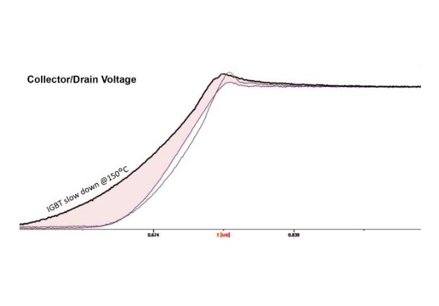
Figure 1: Turn-on switching behavior of Si IGBT vs CoolSiC™ mosfet at 5 kV/μs
For applications such as servomotors and industrial robotic arms, where cooling capability is limited and efficiency important, using CoolSiC™ MOSFETs have huge advantages, especially if size, weight and compact design are key priorities for the system designer.
The long motor cables cause high peak voltages at the motor, which stress the motor isolation system and motor bearings. To protect the drive, manufacturers often stay under the 5 kV/μs switching speed. If a CoolSiC™ mosfet is driven with low dv/dt, its switching losses will increase. However, the CoolSiC™ MOSFET still has more than 50% lower switching losses compared to high-speed IGBTs at 5 kV/μs.
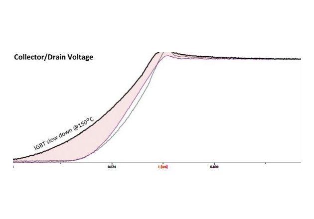
Figure 2: Turn-off switching behavior IGBT vs CoolSiC™ MOSFET at 5 kV/μs7
In addition, CoolSiC™ MOSFETs have temperature-independent switching losses and smaller voltage overshoot, due to smoother current decrease. IGBT switching voltage has higher overshoot, and its switching speed slows down significantly at higher temperatures (see Figure 2). CoolSiC™ MOSFETs can switch with a speed exceeding 60 kV/μs, and there is a way to unleash the potential of the loss reductions. It can be done by implementing a dv/dt filter on the inverter output. In this way, the Semiconductor can switch at maximum speed, and the filter will prevent the motor windings from stressing at high dv/dt and peak voltages. This has already been implemented in highspeed drives. In various studies, dv/dt filters have been presented with an improved filter solution that can be achieved by connecting the dv/dt filter to the middle potential of the DC-link. Using new motors with reinforced insulation systems together with minimized dv/dt filters are ways of making use of the full potential of SiC switches. [5]
Simulation and experimental validation
In order to see the performance of CoolSiC™ devices and understand the behavior of servo drives at different conditions, a simulation study was done, and compared with the experimental test results.
The junction temperature of the devices in a real system is very hard to measure, where normally the case temperature is detected. To have a more accurate estimation of a junction temperature, the simulation is recommended.
To finally confirm the performance of the proposed CoolSiC™ MOSFET discrete solution in comparison with the high-speed IGBT solution, a simulation model based on a Three-Phase B6 topology has been developed to estimate the junction Tj performance and corresponding losses of the inverter.
The results in Figure 3 show that even at 5 kV/μs, the strongly decelerated CoolSiC™ MOSFETs show up to 60% lower loss and 38% lower temperature rise of junction temperature (Tj) in comparison with the high-speed IGBT. This is due to the fact that body diodes have no (or very low) reverse recovery charge (Qrr) and that CoolSiC™ MOSFETs have no tail current, as shown in Figures 1 and 2.
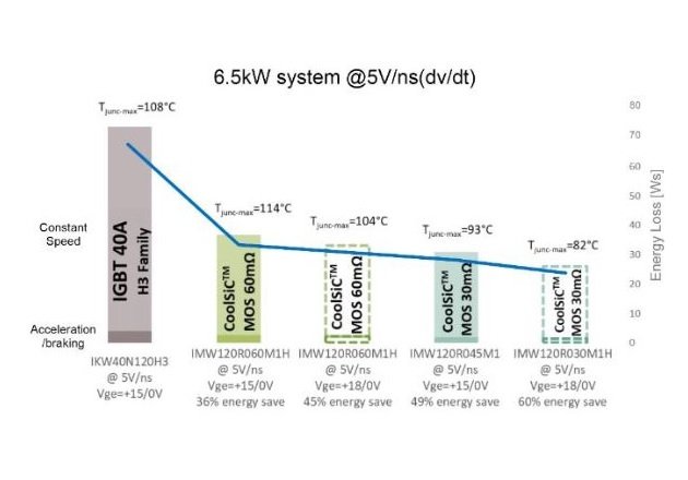
Figure 3: Thermal and loss comparison of CoolSiC™ MOSFET vs high-speed 3 IGBT for a 6.5 kW system at 5 kV/μs (dv/dt) switching speed for constant speed and acceleration/braking mode
New regulations [5] indicate that the switching speed of high-speed drives can be increased up to 8 kV/μs with 16 kHz switching frequency. Due to the much lower overshoot of CoolSiC™ MOSFETs compared to IGBTs, it is possible to run the CoolSiC™ in certain cases even higher. Servo-drive applications normally do not make use of long cables, which also enables faster switching.
When a CoolSiC™ MOSFET is driven with 8 kV/μs (instead of 5 kV/ μs), up to 64% lower losses, and up to 47% lower temperature rise of the Tj, are possible in comparison with a high-speed 3 IGBT, which is shown in Figure 4.
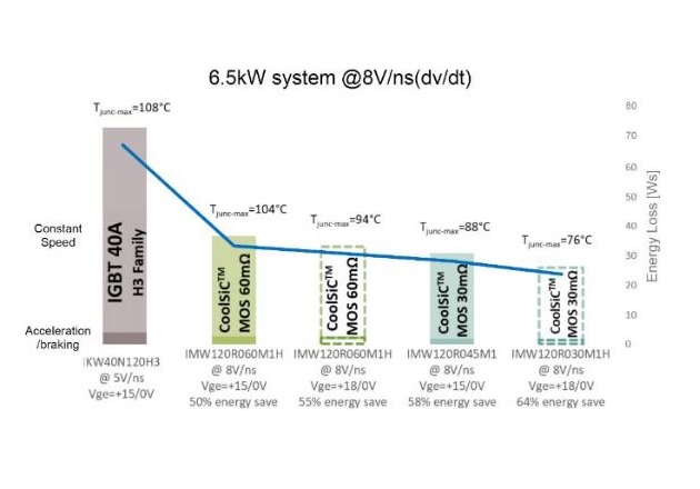
Figure 4: Thermal and loss comparison of CoolSiC™ MOSFET vs high-speed 3 IGBT for 6.5 kW system at 8 kV/μs (dv/dt) switching speed for constant speed and acceleration/braking mode.
Conclusion
The test results and the simulation validation have confirmed that using CoolSiC™ MOSFETs in servo drives leads to 64% loss reduction and 47% lower temperature rise at low switching speeds (5-8 kV/μs).
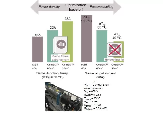
Figure 5: RDS(on) selection example for various target requirements of a servo-drive solution and motor test setup with test condition
By using a 60 mΩ CoolSiC™ MOSFET to replace the 40 A IGBT in a servo-drive application, while keeping the heat sink and dv/dt requirement, the total Semiconductor loss drops by almost half at similar maximum junction temperatures.
CoolSiC loss reduction provides a new degree of flexibility for system improvements:
- Trade-off between output current, Tj, cooling efforts and RDS(on) selection
- The low ΔTj from CoolSiC™ MOSFETs enables passive cooling
References:
[1] Dr. Fanny Björk, Dr. Zhihui Yuan Infineon Technologies AG, Austria. CoolSiC™ SiC MOSFETs: a solution for bridge topologies in Three-Phase power conversion 2019
[2] Sahan Benjamin, Brodt Anastasia Infineon Technologies AG, Germany. Enhancing power density and efficiency of variable speed drives with 1200V SiC T-MOSFET. PCIM Europe 2017, 16 – 18 May 2017, Nuremberg, Germany
[3] Tiefu Zhao, Jun Wang, Alex Q. Huang, Comparisons of SiC MOSFET and Si IGBT Based Motor Drive Systems 2007
[4] S. Tiwari, O.M. Midtgard, T. M. Undeland. SiC MOSFETs for Future Motor Drive Applications 2016
[5] K. Vogel, A. Brodt, A. Rossa “Improve the efficiency in AC-Drives: New Semiconductor solutions and their challenges”, EEMODS 2015
[6] Eval-M5-IMZ120R-SiC https://www.infineon.com/cms/de/product/ evaluation- boards/eval-m5-imz120r-sic/
This article originally appeared in Bodo’s Power Systems magazine.