FF150R12KT3G: Technical Analysis of Infineon’s 1200V 150A IGBT Module
FF150R12KT3G | 1200V 150A Dual IGBT Module | Infineon
Introduction to the FF150R12KT3G Dual IGBT Module
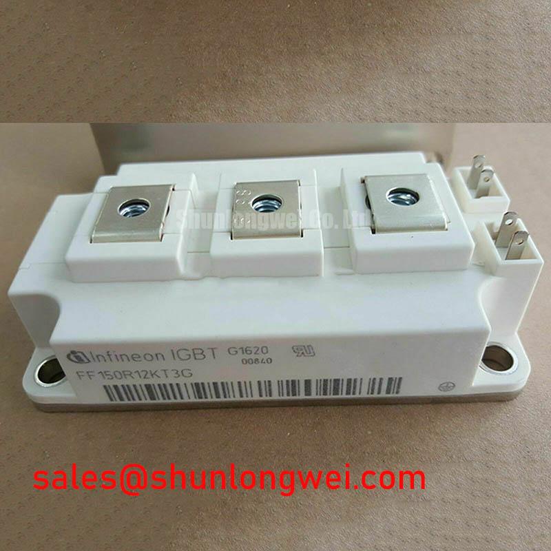
This Infineon device is a 62mm C-Series dual IGBT module engineered for high-reliability power conversion systems. It leverages Infineon’s TRENCHSTOP™ IGBT3 technology to deliver a superior balance of low conduction and switching losses, forming a robust foundation for demanding industrial applications. This technical profile provides an analysis based on the official manufacturer datasheet.
- Core Specifications: 1200V | 150A | VCE(sat) (typ) 1.7V
- Key Advantages: Minimized conduction losses reduce thermal load; controlled switching characteristics lower system EMI.
- Design Focus: Its performance parameters are well-suited for frequency-controlled inverter drives, enabling efficient motor control.
Download the Official FF150R12KT3G Datasheet (PDF)


Technical Analysis: Efficiency and Reliability
The engineering value of the FF150R12KT3G is rooted in its internal chip technology. The TRENCHSTOP™ IGBT3 design provides a low collector-emitter saturation voltage (VCE(sat)) of 1.7V (typical at IC = 150A, Tvj = 25°C). You can think of VCE(sat) as the electrical “friction” the device generates when it’s on; a lower value means less power is wasted as heat. This directly translates to higher system efficiency and reduced requirements for thermal management hardware, allowing for more compact designs.
Beyond static conduction, the module’s dynamic performance is equally critical. The integration of an Emitter Controlled high-efficiency diode ensures soft switching behavior. This “softness” in recovery reduces voltage overshoots and oscillations during turn-off, which is a primary source of electromagnetic interference (EMI). By mitigating EMI at the component level, engineers can often simplify or reduce external snubber and filter circuits, saving both board space and cost.
Optimized Application Scenarios
The specific parameter set of the FF150R12KT3G makes it a strong candidate for several power conversion topologies. Its suitability is determined by how its features address the primary challenges of each application.
- Motor Control and Drives: The module’s robust Safe Operating Area (SOA) and controlled switching characteristics can withstand the inductive loads and dynamic conditions typical in Variable Frequency Drives (VFDs).
- Solar Inverters: High efficiency is paramount in solar applications. The low VCE(sat) directly contributes to maximizing energy harvest by minimizing conversion losses.
- Uninterruptible Power Supply (UPS): The module’s reliability and high current handling capability (up to 225A at TC = 25°C) provide the dependability required to support critical loads.
- Industrial Welding: The fast and efficient switching supports the high-frequency operation needed in modern welding power supplies.
This module is an optimal match for industrial drives where thermal efficiency and operational reliability are primary design drivers.
Key Technical Specifications
| Absolute Maximum Ratings (Tvj = 25°C unless otherwise specified) | |
|---|---|
| Collector-Emitter Voltage (VCES) | 1200 V |
| Continuous DC Collector Current (IC) @ TC=80°C | 150 A |
| Repetitive Peak Collector Current (ICRM), tP=1ms | 300 A |
| Total Power Dissipation (Ptot) @ TC=25°C | 780 W |
| Operating Junction Temperature (Tvj op) | -40 to +125 °C |
| Electrical Characteristics | |
| Collector-Emitter Saturation Voltage (VCE(sat)) (IC=150A, VGE=15V, Tvj=25°C) | 1.70 V (typ) |
| Gate Threshold Voltage (VGE(th)) | 5.0 – 6.5 V |
| Thermal Resistance, Junction-to-Case (RthJC) per IGBT | 0.16 K/W (max) |
Engineer’s FAQ
1. How do I calculate conduction losses for the FF150R12KT3G in my application?
To estimate first-order conduction losses (Pcond), use the formula: Pcond = VCE(sat) × IC × D, where IC is your operating collector current and D is the duty cycle. For accurate results, refer to the VCE(sat) vs. IC characteristic curves in the datasheet to find the saturation voltage at your specific operating current and junction temperature.
2. What is the correct mounting torque for this IGBT module?
The datasheet specifies a mounting torque of 3.0 to 6.0 N·m for the M6 mounting screws. Applying the correct torque is critical. Insufficient torque leads to poor thermal contact with the heatsink, increasing thermal resistance. Excessive torque can warp the module’s baseplate, creating gaps and compromising thermal performance and long-term reliability.
3. What is the primary benefit of the Emitter Controlled diode technology?
The main benefit is achieving “soft” reverse recovery characteristics. This means the diode current falls more gently during turn-off, reducing the rate of current change (di/dt). This behavior minimizes induced voltage spikes and high-frequency EMI, leading to cleaner switching waveforms and improved system-level electromagnetic compatibility (EMC).
Enabling Robust Power System Design
The FF150R12KT3G module offers a well-documented and reliable solution for power system engineers. Its foundation in Infineon TRENCHSTOP™ IGBT3 technology provides a favorable trade-off between conduction and switching losses. This balance enables the design of efficient, thermally stable, and reliable power converters for a range of industrial systems.