A Technical Deep Dive into the Infineon FP75R12KT4_B16 Power Module
## FP75R12KT4_B16: 1200V 75A IGBT PIM Module Analysis
The Infineon FP75R12KT4_B16 is a Power Integrated Module (PIM) that integrates a three-phase inverter, brake chopper, and rectifier into a single EconoPIM™ 3 package. This module leverages TRENCHSTOP™ IGBT4 technology to deliver a balanced performance profile, optimizing for both conduction and switching losses. It provides engineers with a compact, highly integrated solution for developing efficient power conversion systems.
* **Core Specifications**: 1200V | 75A | VCE(sat) 1.85V (typ. @ 25°C)
* **Key Advantages**: Simplifies system design by integrating multiple power stages; facilitates effective thermal management with a copper baseplate.
* **Design Focus**: For engineers specifying components for motor drives, this module’s integrated nature and thermal characteristics streamline the development process.
Download Official Datasheet (PDF)
Technical Deep Dive: Integration and Performance
The primary engineering value of the **FP75R12KT4_B16** lies in its high level of integration. By combining the inverter, brake, and rectifier circuits, the module reduces the number of discrete components required in a system. This leads to a smaller PCB footprint, simplified assembly, and reduced stray inductance, which can be a source of electromagnetic interference (EMI). The module’s internal layout is optimized to manage current paths effectively within the shared EconoPIM™ 3 housing. This integration directly supports the creation of more compact and power-dense power electronics.
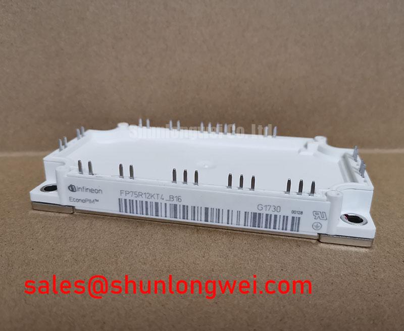
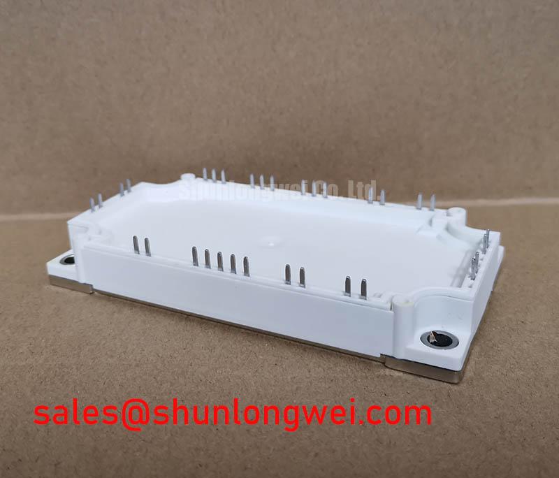
At the core of the module is Infineon’s TRENCHSTOP™ IGBT4 technology. This silicon provides a low collector-emitter saturation voltage (VCE(sat)) of 1.85V at its nominal current and 25°C. This parameter is critical as it directly correlates to conduction losses—the heat generated while the IGBT is in its ‘on’ state. Think of thermal resistance (RthJC) as the width of a pipe for heat to escape; a lower value means a wider pipe. The module’s specified RthJC per IGBT allows engineers to accurately calculate cooling requirements, ensuring the device operates within its safe temperature limits, a concept further explored in guides on mastering IGBT thermal design.
Optimized Application Scenarios
The specific characteristics of the FP75R12KT4_B16 make it suitable for several power conversion applications:
* **Motor Drives**: The integrated three-phase inverter and brake chopper are essential components for controlling AC motors in industrial automation, pumps, and fans.
* **Servo Drives**: For applications requiring precise motion control, the module’s controlled switching characteristics and integrated nature contribute to system reliability and responsiveness.
* **Auxiliary Inverters**: In systems such as commercial vehicles or renewables, this module can serve as a robust power source for auxiliary systems.
* **Industrial Heating and Welding**: The module’s current and voltage ratings are well-suited for the power stages in industrial heating and welding equipment.
This module is best matched for motor drive systems up to 37 kW, where reducing design complexity and ensuring reliable thermal performance are key objectives.
Key Technical Specifications
| Parameter | Value | Conditions |
|---|---|---|
| Collector-Emitter Voltage (V_CES) | 1200 V | T_vj = 25°C |
| Nominal Collector Current (I_C nom) | 75 A | T_C = 95°C, T_vj max = 175°C |
| Collector-Emitter Saturation Voltage (V_CEsat) | 1.85 V (typ) / 2.15 V (max) | I_C = 75 A, V_GE = 15 V, T_vj = 25°C |
| Gate Threshold Voltage (V_GEth) | 5.20 V to 6.40 V | I_C = 2.40 mA, T_vj = 25°C |
| Thermal Resistance, Junction-to-Case (R_thJC) | 0.230 K/W (per IGBT) | – |
| Maximum Operating Junction Temperature (T_vj op) | -40 to 150 °C | – |
Note: All parameters are based on the official manufacturer datasheet. For complete details, refer to the linked PDF.
Engineer’s FAQ
**1. How does the VCE(sat) of the FP75R12KT4_B16 change with temperature?**
The datasheet indicates that VCE(sat) has a positive temperature coefficient. While the typical value is 1.85V at 25°C, it increases to a typical value of 2.15V at 125°C and 2.25V at 150°C. Engineers must use these higher values when calculating conduction losses under real-world operating conditions.
**2. What is the function of the integrated NTC thermistor?**
The integrated NTC (Negative Temperature Coefficient) thermistor provides a means for real-time temperature monitoring of the module’s baseplate. This data is critical for the control system to implement over-temperature protection, preventing thermal runaway and enhancing overall system reliability. The benefits of such integration are often discussed in the context of IGBT module safety.
**3. What are the key considerations for mounting this module to a heatsink?**
For effective thermal transfer, the datasheet specifies using a thermal grease with a thermal conductivity of approximately 1 W/(m·K). The mounting torque for the electrical terminals and the mechanical mounting screws must adhere to the values specified in the datasheet to prevent mechanical stress and ensure a low thermal resistance path. Proper mounting is fundamental to IGBT reliability.
**4. Does the integrated rectifier support both single-phase and three-phase input?**
The internal topology consists of a full three-phase diode bridge rectifier. It is designed and rated for three-phase AC input to generate the DC bus voltage for the inverter and brake chopper sections.
Design Enablement
The FP75R12KT4_B16 provides a robust, integrated foundation for power systems. Its combination of proven IGBT4 technology and a multi-function topology in a standard industrial package enables engineers to meet demands for power density and simplified manufacturing without compromising on thermal performance.