A Technical Review of the Fuji 2MBI150VB-120-50: Low Loss Meets High Reliability
Fuji 2MBI150VB-120-50 IGBT Module | 1200V 150A V-Series
Introduction and Core Highlights
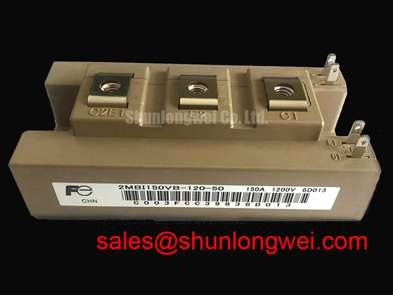
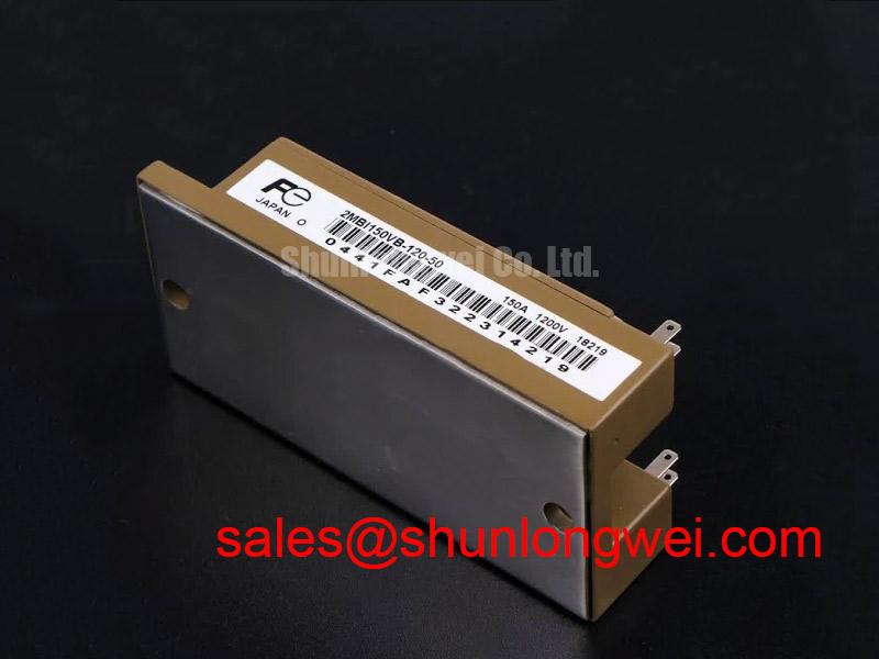
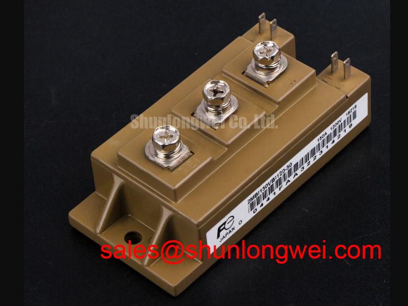
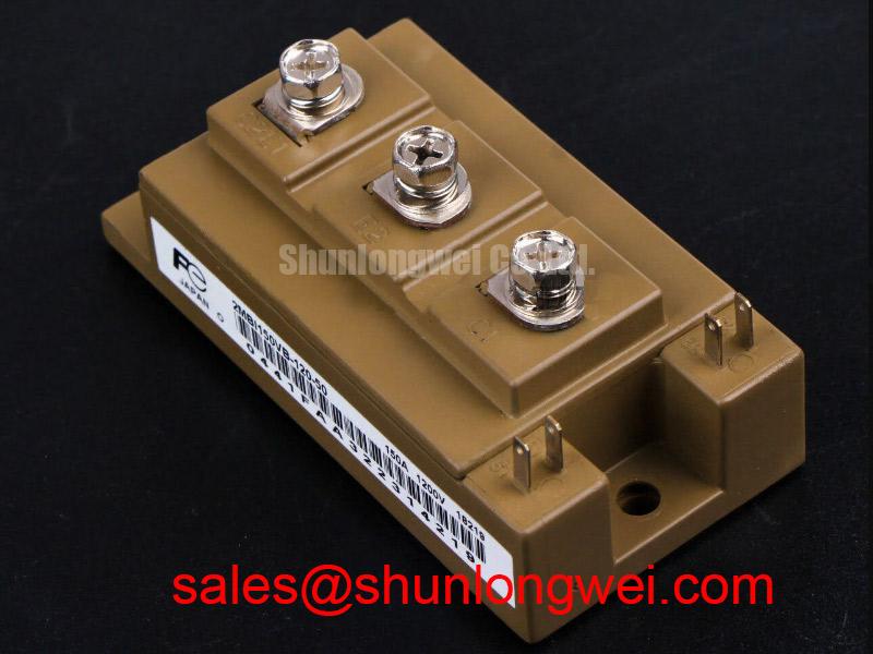
The Fuji Electric 2MBI150VB-120-50 is a V-Series dual IGBT module engineered to deliver a superior balance of low power loss and high operational reliability. Its core value proposition is the combination of a low collector-emitter saturation voltage (VCE(sat)) and a Square Reverse Bias Safe Operating Area (RBSOA), which enables robust performance in demanding power conversion applications. This design directly addresses the need for higher efficiency by minimizing conduction losses, thereby reducing the thermal load on system cooling components.
- Core Specifications: 1200V | 150A | VCE(sat) 1.70V (typ)
- Key Advantages: Minimized conduction losses, high turn-off ruggedness for inductive loads.
Download Official Datasheet (PDF)
Technical Analysis of V-Series Performance
A defining characteristic of the 2MBI150VB-120-50 is its low collector-emitter saturation voltage (VCE(sat)), specified at a typical value of 1.70V at its rated current of 150A. This parameter is crucial as it directly determines the conduction power loss (P = VCE(sat) * IC). You can think of thermal resistance like the width of a water pipe; a lower value, such as the 0.16 °C/W per IGBT chip specified here, means heat can flow away more easily, preventing the device from overheating. By minimizing VCE(sat), the module generates less heat during operation, which can lead to smaller heatsink requirements and increased overall system efficiency.
The module’s datasheet highlights a “Square RBSOA,” a feature of significant engineering importance for system reliability. The RBSOA defines the voltage and current limits the IGBT can safely handle during turn-off. A “square” shape indicates that the device can withstand high collector currents even at its maximum collector-emitter voltage. This is particularly valuable in applications with high stray inductance, like motor drives, where voltage overshoots can occur. The robust RBSOA provides a larger safety margin, protecting the module from destructive failure during hard switching events. For more on IGBT reliability, see our analysis of common failure modes.
Optimized Application Scenarios
The technical characteristics of this module make it well-suited for several specific power conversion roles:
- AC & Servo Drives: The Square RBSOA provides the necessary ruggedness to handle the demanding inductive loads and potential voltage overshoots common in motor control.
- Uninterruptible Power Supplies (UPS): The low VCE(sat) of 1.70V (typ.) contributes directly to lower conduction losses, enhancing the overall efficiency of the UPS system.
- General Purpose Inverters: Its balanced profile of low losses, robust construction, and standard package design makes it a versatile component for various inverter topologies. The integrated NTC thermistor further simplifies thermal management.
This module’s blend of low-loss V-Series technology and high turn-off ruggedness makes it an excellent match for mid-power systems prioritizing efficiency and operational reliability.
Key Specification Parameters
| Absolute Maximum Ratings (Tc=25°C unless otherwise specified) | |
|---|---|
| Collector-Emitter Voltage (Vces) | 1200V |
| Gate-Emitter Voltage (Vges) | ±20V |
| Continuous Collector Current (Ic) | 150A (at Tc=80°C) |
| Peak Collector Current (Icp) | 300A (1ms pulse) |
| Max Power Dissipation (Pc) | 690W per IGBT |
| Electrical & Thermal Characteristics (Tj=25°C) | |
| Collector-Emitter Saturation Voltage (VCE(sat)) | 1.70V (Typ) / 2.20V (Max) at Ic=150A |
| FWD Forward Voltage (VF) | 1.75V (Typ) / 2.25V (Max) at Ie=150A |
| Thermal Resistance, Junction to Case (Rth(j-c)) – IGBT | 0.16 °C/W |
| Thermal Resistance, Junction to Case (Rth(j-c)) – FWD | 0.28 °C/W |
Engineer’s Frequently Asked Questions (FAQ)
1. What is the engineering benefit of the “Square RBSOA” for the 2MBI150VB-120-50?
A Square RBSOA provides a wider safe operating margin during turn-off. It ensures the module can safely switch off its maximum rated current even when the full collector-emitter voltage is applied, a condition often caused by stray inductance in the circuit. This makes the device more robust and less susceptible to failure in real-world applications like motor drives.
2. How do I use the datasheet’s thermal resistance (Rth) values for heatsink selection?
The key value is Rth(j-c), the junction-to-case thermal resistance (0.16 °C/W for the IGBT). To select a heatsink, first calculate the power dissipation (Ploss). Then, use the formula: Rth(c-a) = (Tj_max – Ta) / Ploss – Rth(j-c), where Tj_max is the maximum junction temperature (175°C), and Ta is the ambient temperature. The calculated Rth(c-a) is the maximum thermal resistance your heatsink and thermal interface material combination can have.
3. What is the recommended gate drive voltage?
The datasheet specifies the gate-emitter voltage (Vges) absolute maximum rating as ±20V. For optimal performance, the electrical characteristics are tested with a Vge of +15V for turn-on and -15V for turn-off. Operating within these recommended levels is essential for reliable switching and longevity.
4. Is this module suitable for high-frequency applications?
The 2MBI150VB-120-50 is part of Fuji’s V-Series, which is optimized for a balance between low conduction losses and switching performance. With total switching energy (Eon+Eoff) of 24 mJ for the IGBT, it is suitable for applications in the lower to medium kHz range. For very high-frequency designs, engineers should perform detailed loss calculations to ensure thermal limits are not exceeded.
Concluding Statement
The 2MBI150VB-120-50 provides a robust and efficient foundation for power conversion systems. Its V-Series architecture, focused on achieving low VCE(sat) while maintaining a rugged operational envelope, empowers engineers to design more compact, reliable, and energy-efficient power solutions for industrial applications.