Infineon FF900R12IE4: A Technical Review of a High-Power IGBT Module
## FF900R12IE4 1200V 900A Dual IGBT Module by Infineon
The Infineon FF900R12IE4 is a high-power PrimePACK™ 2 dual IGBT module engineered for high-reliability power conversion systems. It leverages Trench/Fieldstop IGBT4 and Emitter Controlled 4 diode technology to provide a robust solution for demanding industrial applications. This module’s primary value is its ability to manage very high currents with notable efficiency, simplifying thermal management in high-power density designs.
* **Core Specifications**: 1200V | 900A | VCE(sat) (typ.) 1.7V
* **Key Advantages**: Low switching losses, high short-circuit capability, and a package design that supports high power and thermal cycling.
* **Engineering Focus**: The FF900R12IE4 is specified for systems requiring high DC stability and robust performance across an extended operating junction temperature up to 150°C.
Download the Official FF900R12IE4 Datasheet (PDF)
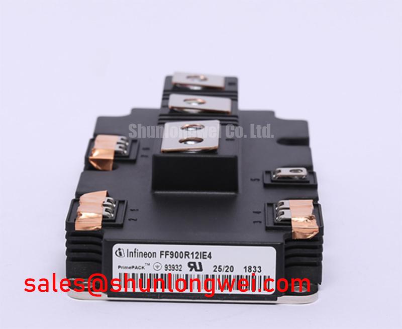

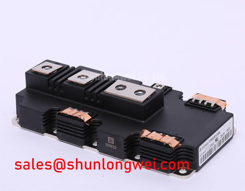

Technical Analysis for High-Power Systems
The engineering value of the FF900R12IE4 is rooted in its balance of high current capability and thermal efficiency. The core of this is the Trench/Fieldstop IGBT4 technology, which enables a low collector-emitter saturation voltage (VCE(sat)) of 1.7V (typical) at its nominal current of 900A. A low VCE(sat) is like reducing friction in a mechanical system; it directly minimizes the power lost as heat during the on-state (conduction losses). This reduction in waste heat allows for smaller heatsinks or higher operational power output for a given cooling system.
Effective thermal management is critical at this power level. The module’s thermal resistance from junction to case (RthJC) is specified at a maximum of 0.049 K/W for the IGBT. This parameter can be imagined as the width of a pipe for heat to escape the semiconductor die. The low thermal resistance of the FF900R12IE4 ensures an efficient heat transfer pathway to the heatsink, a crucial factor in preventing the device from exceeding its maximum operating junction temperature of 175°C under load. This robust thermal design is fundamental to the module’s long-term reliability in demanding power cycling applications.
The PrimePACK™ 2 package itself contributes to system reliability. It is designed for low stray inductance, which is essential for minimizing voltage overshoots during high-speed switching events. This electrical characteristic, combined with a high short-circuit withstand time of 10 µs, provides a significant margin of safety, allowing for the implementation of robust protection circuits in the gate drive system. The integrated NTC thermistor further aids reliability by enabling direct monitoring of the module’s temperature.
Optimized Application Scenarios
The specific characteristics of the FF900R12IE4 make it a strong candidate for several high-power applications:
- High-Power Motor Drives: Its 900A nominal current rating and high robustness are ideal for controlling large AC induction motors in industrial settings like conveyor systems, pumps, and compressors.
- Renewable Energy Inverters: In large-scale solar and wind turbine systems, the module’s low switching and conduction losses, enabled by the IGBT4 technology, contribute to higher overall energy conversion efficiency.
- Uninterruptible Power Supplies (UPS): For data centers and critical industrial facilities, the module’s high DC stability and current handling capacity ensure reliable power backup when it’s needed most.
- Traction Drives: The module’s robust mechanical and thermal cycling capability makes it suitable for the demanding environments of light rail and commercial electric vehicle powertrains.
Its combination of high current handling and efficiency makes it an optimal fit for three-phase inverter designs operating well above 250 kW.
Key Specifications of the FF900R12IE4
| Parameter | Conditions | Value | |
|---|---|---|---|
| Maximum Rated Values | Collector-Emitter Voltage (V_CES) | T_vj = 25°C | 1200 V |
| Continuous DC Collector Current (I_Cnom) | T_H = 60°C, T_vj max = 175°C | 900 A | |
| Repetitive Peak Collector Current (I_CRM) | t_p = 1 ms | 1800 A | |
| Operating Junction Temperature (T_vj op) | -40 to +150 °C | ||
| IGBT, Inverter – Characteristic Values | Collector-Emitter Saturation Voltage (V_CEsat) | I_C = 900 A, V_GE = 15 V, T_vj = 25°C | 1.70 V (typ.) |
| Total Switching Energy (E_tot) | I_C = 900 A, V_CE = 600V, V_GE = ±15V, R_G = 1.1 Ω, T_vj = 150°C | 265 mJ (typ.) | |
| Short Circuit Withstand Time (t_psc) | V_GE ≤ 15 V, V_CC = 800 V, T_vj ≤ 150°C | 10 µs | |
| Diode, Inverter – Characteristic Values | Forward Voltage (V_F) | I_F = 900 A, V_GE = 0 V, T_vj = 25°C | 1.65 V (typ.) |
| Reverse Recovery Energy (E_rec) | I_F = 900 A, V_CE = 600V, di/dt = 11000 A/µs, T_vj = 150°C | 160 mJ (typ.) | |
| Module Characteristics | Insulation Test Voltage (V_ISOL) | RMS, f = 50 Hz, t = 1 min | 4.0 kV |
| Thermal Resistance, Junction-to-Case (R_thJC) | per IGBT | 0.049 K/W (max) | |
Note: These parameters are for reference. Please consult the official datasheet for complete and verified specifications.
Engineer’s FAQ for FF900R12IE4
1. What are the main thermal design considerations for the FF900R12IE4?
The primary consideration is ensuring the junction temperature remains within the -40°C to 150°C operating range. This requires selecting a heatsink with sufficiently low thermal resistance. The calculation must account for the module’s internal thermal resistance (R_thJC), the thermal resistance of the Thermal Interface Material (TIM), and the heatsink’s resistance to ambient (R_thHA). Total power losses (conduction and switching) must be calculated based on the specific application’s current, voltage, and switching frequency to determine the required cooling performance.
2. What is the recommended gate driver voltage?
The datasheet specifies characteristic values using a gate-emitter voltage (V_GE) of +15V for turn-on and -15V for turn-off. A +15V gate voltage ensures the IGBT is fully saturated, minimizing on-state losses. A negative turn-off voltage of -15V provides a strong buffer against parasitic turn-on caused by Miller capacitance, enhancing noise immunity, which is critical in high-power, fast-switching environments. A properly designed gate drive is essential for performance and reliability.
3. What does the 10 µs short-circuit withstand time imply for system design?
This rating means the device can survive a direct short-circuit for up to 10 microseconds before catastrophic failure. The system’s protection circuitry, typically managed by the gate driver IC, must detect the short-circuit condition (usually via desaturation detection) and safely shut down the IGBT well within this 10 µs window.
4. Can FF900R12IE4 modules be connected in parallel for higher current?
Yes, but successful IGBT paralleling requires careful design. The positive temperature coefficient of VCE(sat) helps to balance current sharing between modules. However, it is critical to ensure a symmetrical busbar layout to equalize stray inductances and to use individual gate resistors for each module to prevent oscillations. The datasheet provides specific application notes on this topic.
Enabling High-Efficiency Power Conversion
The FF900R12IE4 module provides the technical foundation for developing power-dense and efficient inverters. Its integration of low-loss IGBT4 silicon with a thermally efficient and electrically robust package allows engineers to push performance boundaries in motor drives, renewable energy systems, and other high-current applications. This module addresses the core engineering challenge of managing high power while maintaining system reliability and efficiency.