CM400DY-24A IGBT Module: A Technical Review for Power System Design
CM400DY-24A Mitsubishi IGBT Module | 1200V 400A Dual
Introduction and Core Highlights
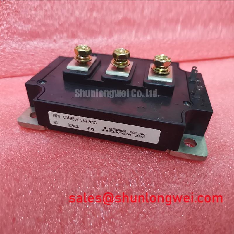
The Mitsubishi CM400DY-24A is a high-power dual IGBT module that provides a robust foundation for demanding power conversion systems. Its design focuses on delivering high current capacity with efficient thermal performance, enabling the development of compact and reliable inverters and motor drives. A key aspect of its performance is the careful balance between conduction losses and switching characteristics, which is critical for managing heat dissipation in high-current applications.
- Core Specifications: 1200V | 400A | VCE(sat) 2.7V (max)
- Key Advantages: High power density simplifies inverter design, and low thermal resistance improves system reliability.
For complete specifications and performance curves, refer to the official documentation.
Download the Official CM400DY-24A Datasheet (PDF)


Technical Analysis for System Design
A primary factor in power module performance is the management of energy losses, which manifest as heat. The CM400DY-24A specifies a maximum collector-emitter saturation voltage (VCE(sat)) of 2.7V at its nominal 400A rating and a junction temperature of 125°C. This parameter is crucial as it directly determines conduction losses during the on-state. A controlled VCE(sat) value ensures that less power is dissipated as heat, which contributes to higher overall system efficiency and reduced demand on the cooling system.
Effective heat extraction is governed by the module’s thermal resistance. The datasheet specifies a junction-to-case thermal resistance (Rth(j-c)) of 0.085°C/W for the IGBT portion. This value can be imagined as the width of a pipe for heat flow; a lower value signifies a wider pipe, allowing heat to transfer more efficiently from the active silicon to the module’s baseplate. This efficient heat transfer is fundamental to maintaining the junction temperature within safe operating limits, directly impacting the module’s reliability and operational lifespan. For a deeper understanding of this process, see our guide to mastering IGBT thermal design.
System robustness is further defined by the Safe Operating Area (SOA) curves provided in the datasheet. The Reverse Bias Safe Operating Area (RBSOA) delineates the voltage and current boundaries the device can withstand during turn-off events. Adhering to these limits is critical for preventing device failure in applications with inductive loads, such as motor drives. The CM400DY-24A provides these curves to enable engineers to design resilient systems that can handle real-world operational stresses without degradation.
Optimized Application Scenarios
The electrical and thermal characteristics of the CM400DY-24A make it a strong candidate for a range of high-power industrial applications.
- General Purpose Inverters: Its 400A current rating and 1200V blocking voltage are well-suited for industrial inverter applications requiring high power throughput.
- AC Motor Drives: The dual (half-bridge) configuration is the standard building block for three-phase motor control, simplifying inverter topology.
- Uninterruptible Power Supplies (UPS): The module’s ability to handle high currents ensures reliable power delivery in critical backup systems.
- Welding Equipment: The device’s robust thermal performance and high current capacity can effectively manage the pulsed power demands of welding power supplies.
This module is an optimal match for systems requiring robust 400A switching with standard industrial-level thermal and electrical isolation.
Key Specification Parameters
| Key Electrical & Thermal Specifications (Tj = 25°C unless otherwise noted) | |
|---|---|
| Parameter | Value |
| Collector-Emitter Voltage (VCES) | 1200V |
| Collector Current (IC) | 400A |
| Collector-Emitter Saturation Voltage (VCE(sat)) (IC=400A, Tj=125°C) | 2.7V (Max) |
| Gate-Emitter Threshold Voltage (VGE(th)) | 5.5V to 7.5V |
| Isolation Voltage (Viso, AC 1 min.) | 2500Vrms |
| Thermal Resistance (Rth(j-c), IGBT) | 0.085°C/W (Per 1/2 Module) |
| Thermal Resistance (Rth(j-c), Diode) | 0.16°C/W (Per 1/2 Module) |
Engineer’s FAQ
- How do I determine the required heatsink performance for the CM400DY-24A?
- To specify a heatsink, you must first calculate the total power dissipation (conduction and switching losses) based on your application’s specific conditions using the graphs in the datasheet. Then, use the formula Rth(c-a) ≤ (Tj_max – Ta) / P_total – Rth(j-c). Use the module’s max junction temperature (Tj_max = 150°C), your maximum ambient temperature (Ta), and the Rth(j-c) value of 0.085°C/W. The result, Rth(c-a), is the maximum thermal resistance your heatsink-to-ambient path can have.
- What are the specified mounting torque values for this module?
- According to the datasheet, both the main terminal screws (M8) and the mounting screws (M6) have a recommended torque range of 3.5 to 6.5 N·m. Applying the correct torque is critical for ensuring low-resistance electrical and thermal connections without inducing mechanical stress on the module’s isolated baseplate. You can learn more about the role of isolated baseplates in our technical articles.
- Is the CM400DY-24A suitable for high-frequency applications like induction heating?
- This module is designed for general-purpose inverter and motor drive applications, which typically operate in the low-to-mid kHz range. The datasheet provides switching energy values (Eon, Eoff) of 80mJ and 95mJ respectively under specified test conditions. For higher frequency systems (>20 kHz), modules specifically designated as “high-speed” may offer lower switching losses, which become the dominant source of heat at higher frequencies.
- What protects the IGBT from inductive voltage spikes when it turns off?
- The module includes an integrated free-wheeling diode (FWD) connected in anti-parallel with each IGBT. When an IGBT turns off, this diode provides a path for the current flowing through an inductive load (like a motor winding), preventing a large voltage spike across the IGBT. The FWD’s forward voltage (VEC) is specified as 3.0V maximum in the datasheet. Our article on the role of the free-wheeling diode provides more detail.
Concluding Statement
The Mitsubishi CM400DY-24A IGBT module delivers a well-balanced combination of high current capability, 1200V blocking voltage, and efficient thermal characteristics. Its industry-standard packaging and proven performance provide engineers with a reliable and straightforward component for implementing high-power inverter and motor control systems.