Infineon FZ1000R16KF4: A Technical Analysis for High-Power Applications
Infineon FZ1000R16KF4 1600V 1000A IGBT Module
Introduction to the FZ1000R16KF4 High-Power IGBT Module
The Infineon FZ1000R16KF4 is a high-power IGBT module engineered for high-current chopper and DC-DC converter applications where performance and reliability are critical. It delivers exceptional power handling and superior thermal performance by combining proven silicon technology with a robust mechanical design. This module is a cornerstone component for systems in industrial drives, renewable energy, and traction that demand a balance of high current capability, voltage resilience, and long-term operational endurance.
- Core Specifications: 1600V | 1000A | VCE(sat) (typ) 2.20V
- Key Advantages: Facilitates efficient thermal management and provides high current density for powerful and compact inverter designs.
This module’s design directly addresses how to manage the significant heat generated in high-current applications, a primary concern for power system engineers.
Download Official Datasheet (PDF)
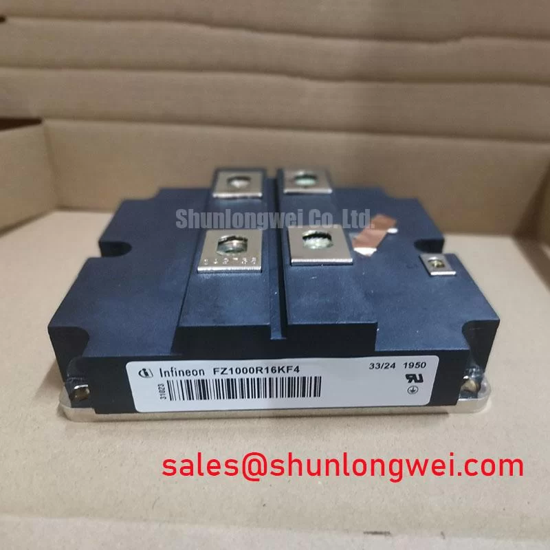
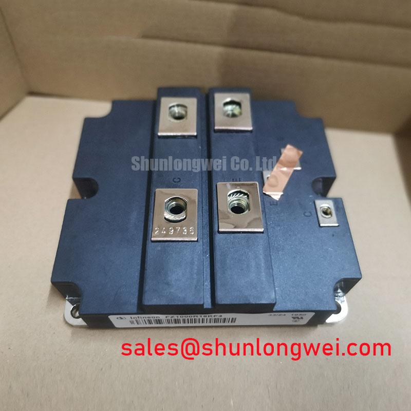
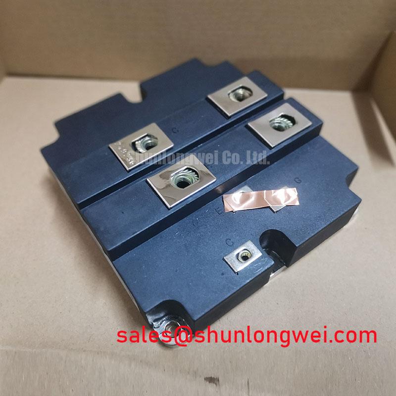
Technical Analysis for System Integration
The performance of the FZ1000R16KF4 is founded on Infineon’s reliable Trench/Field-Stop IGBT technology. This silicon design achieves a balanced trade-off between conduction losses, indicated by the typical VCE(sat) of 2.20V at nominal current, and switching losses. For engineers, this balance is crucial for minimizing total power dissipation, which in turn reduces the demand on the cooling system and improves overall energy efficiency. This is a key factor in applications like solar inverters where every percentage of efficiency matters.
Thermal management is central to the module’s design. The IHV B package features an Aluminum Silicon Carbide (AlSiC) baseplate combined with an Aluminum Nitride (AlN) substrate. Think of the thermal resistance as the width of a pipe for heat to escape; the AlSiC/AlN structure creates a very wide pipe. This construction provides excellent thermal conductivity and a Coefficient of Thermal Expansion (CTE) that is closely matched to the silicon itself. This synergy enhances the module’s ability to withstand repeated power and thermal cycling, ensuring mechanical integrity and a long operational life in applications with frequent temperature swings.
Optimized Application Scenarios
The FZ1000R16KF4 is engineered for specific high-power, single-switch topologies:
- Braking Choppers for VFDs: In applications like cranes, elevators, or conveyors, this module can reliably dissipate immense regenerative energy from the motor. Its high current rating and robust Safe Operating Area (SOA) handle the intense, cyclical braking pulses.
- High-Power DC-DC Converters: The module’s efficiency and thermal stability make it a strong candidate for the core switching component in industrial DC-DC power supplies and chargers.
- Renewable Energy Systems: Suitable for use in DC coupling and chopper stages within large-scale wind turbines and central solar inverters, where its high voltage and current ratings are paramount.
With its 1000A continuous current rating and robust thermal design, this module is best matched for systems requiring high-reliability energy management and dissipation.
Key Specifications of the FZ1000R16KF4
| Parameter | Value | |
|---|---|---|
| Maximum Ratings | ||
| Collector-Emitter Voltage (VCES) | 1600 V | |
| Continuous Collector Current (IC) @ TC=80°C | 1000 A | |
| Total Power Dissipation (Ptot) @ TC=25°C | 5350 W | |
| Short Circuit Withstand Time (tSC) | 10 µs | |
| Electrical & Thermal Characteristics | ||
| Collector-Emitter Saturation Voltage (VCE(sat)) @ IC=1000A, Tvj=125°C | 2.20 V (typ) | |
| Isolation Voltage (Visol) | 3400 V (RMS, 50 Hz, 1 min) | |
| Package | IHV B | |
Engineer FAQ
What are the main considerations for the thermal design when using the FZ1000R16KF4?
The primary goal is to efficiently extract heat from the module’s baseplate. Due to its 5350W power dissipation capability, selecting a heatsink with very low thermal resistance is essential. Proper mounting technique, including the correct clamping force and the application of a high-quality thermal interface material, is critical to minimize the case-to-heatsink thermal resistance and ensure the junction temperature remains within its safe operating limits.
How does the IHV B package facilitate busbar mounting?
The IHV B package features large, flat power terminals with a standardized layout. This design allows for direct, low-inductance busbar connections. A well-designed busbar minimizes stray inductance, which is crucial for reducing voltage overshoot during high-speed switching and is a key topic in IGBT switching performance.
What is the specified short-circuit withstand time (tSC)?
The module is rated for a short-circuit withstand time of 10 microseconds (µs). This means the gate drive protection circuit must detect the fault and turn off the IGBT well within this timeframe to prevent catastrophic failure.
Enabling High-Power System Design
This module provides a validated foundation for developing high-current power electronic systems. The FZ1000R16KF4‘s combination of high power density, proven Trench/Field-Stop IGBT technology, and a thermally efficient package allows engineers to build robust and powerful converters with confidence in their long-term operational stability.