Fuji 2MBI25L-120 IGBT Module: A Technical Review
Fuji 2MBI25L-120 IGBT Module: A 1200V 25A Dual Solution
Technical Introduction to the Fuji Electric 2MBI25L-120 IGBT Module
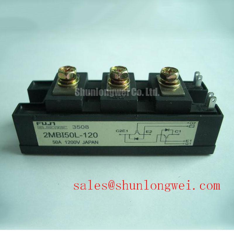
The Fuji Electric 2MBI25L-120 is a dual IGBT module from their L-Series, engineered to deliver a balanced combination of efficiency and reliability for industrial power conversion systems. This module integrates a half-bridge circuit (two IGBTs with corresponding freewheeling diodes) into a single standard package, simplifying system design for engineers. Its core value lies in providing a robust, thermally stable switching block for applications demanding high voltage tolerance and moderate current handling.
- Core Specifications: 1200V | 25A | VCE(sat) 2.4V (typ)
- Key Strengths: Low conduction losses, simplified inverter leg design
- Design Benefit: Enables more compact and efficient motor drives and power supplies by reducing component count and simplifying thermal management.
Download Official Datasheet (PDF)

Technical Analysis for System Integration
The primary advantage of the 2MBI25L-120 is its focus on minimizing conduction losses, a critical factor for overall system efficiency. This is quantified by its low collector-emitter saturation voltage (VCE(sat)), which has a typical value of 2.4V at its nominal 25A current (Tj=125°C). You can think of thermal resistance (Rth(j-c)) like the width of a pipe; a lower value, such as this module’s 0.8°C/W per IGBT, means heat can flow away from the semiconductor chip more easily, preventing overheating and improving long-term reliability. This characteristic directly reduces the burden on the system’s cooling hardware.
The integrated half-bridge topology provides a distinct engineering advantage over using discrete components. By housing two IGBTs and two freewheeling diodes in a single module, the parasitic inductance within the switching loop is minimized. Lower inductance reduces voltage overshoots during high-speed switching events, leading to a more stable and reliable operation. This integrated approach, as detailed in our guide to PIM vs. discrete IGBTs, simplifies PCB layout, reduces assembly complexity, and contributes to a more compact final product.
Optimized Application Scenarios
The specific characteristics of the 2MBI25L-120 make it a strong candidate for several industrial applications:
- Small Motor Drives (VFDs): The 2-in-1 configuration is the fundamental building block for one leg of a three-phase inverter. Its 25A rating is well-suited for controlling fractional to low horsepower AC motors with high efficiency.
- Uninterruptible Power Supplies (UPS): The 1200V breakdown voltage provides a significant safety margin for battery-backed systems, ensuring robust performance and device integrity during power line fluctuations.
- Welding Power Supplies: The module’s robust Safe Operating Area (SOA) and the inclusion of a fast, soft-recovery freewheeling diode (FWD) are beneficial for the pulsed, high-current demands found in welding applications.
- Industrial Power Supplies: In switched-mode power supplies (SMPS) and booster circuits, its balanced switching and conduction performance helps designers achieve high efficiency targets.
This module is best matched for power conversion systems up to ~10kW where proven reliability and thermal efficiency are primary design criteria.
Key Technical Specifications of the 2MBI25L-120
| Absolute Maximum Ratings (Tc=25°C) | |
|---|---|
| Collector-Emitter Voltage (VCES) | 1200V |
| Continuous Collector Current (IC) @ Tc=80°C | 25A |
| Total Power Dissipation (PC) @ Tc=25°C | 200W |
| Operating Junction Temperature (Tj) | -40 to +150°C |
| Electrical & Thermal Characteristics (Tj=125°C unless noted) | |
| Collector-Emitter Saturation Voltage (VCE(sat)) (Max @ 25A) | 2.8V |
| Gate-Emitter Threshold Voltage (VGE(th)) | 5.0V to 8.0V |
| Thermal Resistance, Junction to Case (Rth(j-c)) per IGBT | 0.8 °C/W |
| Thermal Resistance, Junction to Case (Rth(j-c)) per FWD | 1.3 °C/W |
Engineer’s FAQ
What are the primary considerations for thermal design with the 2MBI25L-120?
The key parameter is the junction-to-case thermal resistance (Rth(j-c)), specified as 0.8°C/W for the IGBT and 1.3°C/W for the diode. To ensure the junction temperature remains below the 150°C maximum, engineers must calculate total power loss (conduction + switching) and use this Rth value to determine the required heatsink performance. Effective IGBT thermal design also requires proper application of thermal interface material and adherence to the specified mounting torque.
What gate driver configuration is recommended for this module?
For optimal performance, a gate driver capable of providing a +15V turn-on voltage and a negative turn-off voltage (e.g., -5V to -10V) is recommended. The negative voltage ensures a strong turn-off, preventing parasitic turn-on events caused by high dv/dt, a topic explored in our guide to enhancing IGBT noise immunity.
How does the integrated half-bridge in the 2MBI25L-120 benefit a motor drive design?
It significantly simplifies the power stage construction. Instead of managing the layout and mounting of four separate discrete components (two IGBTs, two diodes) for one inverter leg, you have a single, thermally optimized module. This reduces assembly time, minimizes PCB routing complexity, lowers stray inductance, and ultimately contributes to a more reliable and compact Variable Frequency Drive (VFD).
The 2MBI25L-120 provides a foundational building block for industrial power electronics, offering a straightforward path to creating efficient and durable systems by leveraging Fuji Electric’s established L-Series technology in a compact, integrated format.