SKiip 83AC121SMT10: The Solder-Free 1200V 15A IGBT Module for Robust Inverter Designs
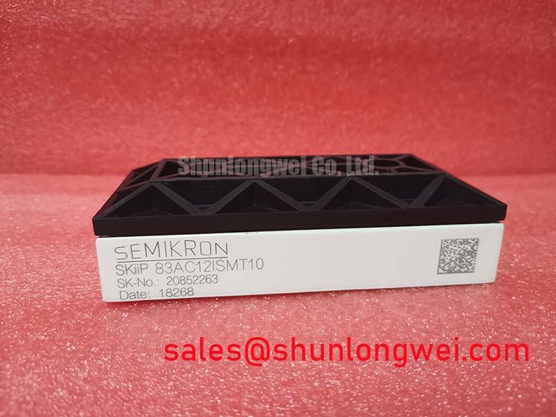
SKiip 83AC121SMT10 Semikron 1200V 15A IGBT Module
The SKiip 83AC121SMT10 is an integrated 1200V, 15A three-phase bridge inverter module optimized for robust power conversion. Utilizing Semikron’s signature solder-free spring contact technology, this module eliminates terminal solder fatigue under extreme thermal and mechanical stresses. The baseplate-less MiniSKiiP package enables a highly compact footprint, making it ideal for variable speed drives and inverter designs where space is at a premium.
- Key Specifications: 1200V Rated Voltage | 15A Nominal Collector Current (Ic) | 1.80V Low VCE(sat)
- Primary Benefits: Eliminates thermal expansion mismatch failure points; simplifies thermal interface design directly to the heatsink.
- Engineering Focus: Resolves the classic solder-joint degradation issues typical in highly cyclical industrial operating environments.
Download Semikron MiniSKiiP Datasheet (PDF)

Solder-Free Technology and Direct Heatsink Thermal Coupling
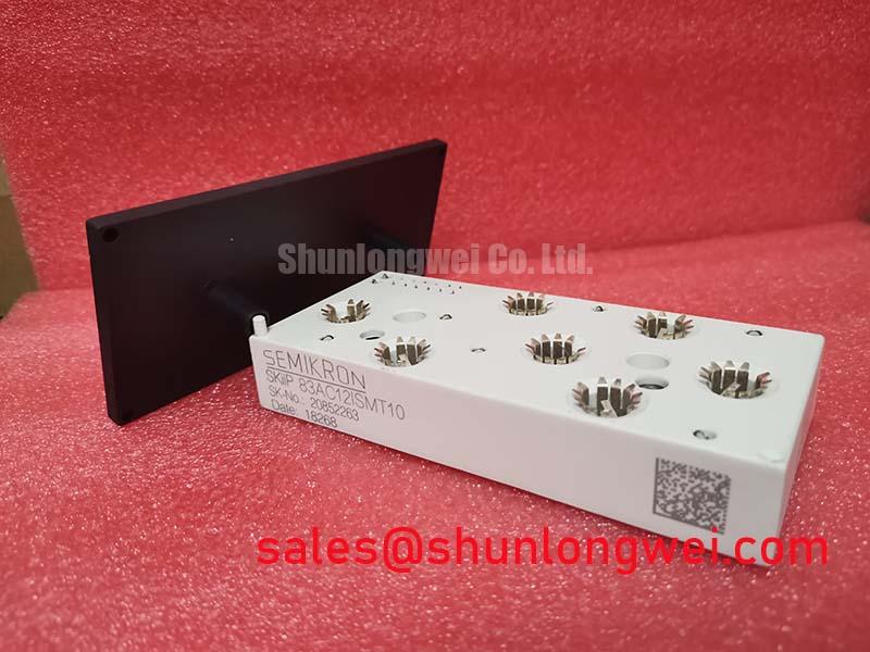
At the core of the SKiip 83AC121SMT10 is its solder-free spring contact assembly. Traditional power modules use soldered pins that degrade over time due to mismatched coefficients of thermal expansion. The spring-loaded contacts of the SKiip 83AC121SMT10 absorb thermomechanical expansion, maintaining constant pressure against the control board. For a deeper look at its construction and spring integrity, consult our comprehensive SKiip 83AC121SMT10 technical review.
This module also features a baseplate-less architecture. To understand this design, imagine putting a hot pan directly onto a cold metal countertop versus placing it on a thick copper plate first. By removing the bulky copper baseplate, the module transfers heat directly from the ceramic substrate to the heatsink. This significantly reduces thermal resistance and prevents thermal hotspots.

The module integrates trench-gate IGBTs that utilize the latest trench gate evolution to maintain a low saturation voltage. Additionally, an integrated NTC temperature sensor provides real-time thermal telemetry. This sensor enables the gate driver to implement over-temperature shutdown before thermal runaway occurs.
Optimized Application Scenarios
- Variable Frequency Drives (VFDs): Spring-loaded terminals withstand continuous vibrations and mechanical shocks in motor control applications.
- Industrial Servo Drives: Highly consistent thermal profiles allow precise torque control under dynamic, fast-cycling loads.
- Solar Micro-Inverters: The 1200V blocking threshold provides exceptional margin in grid-tied solar conversion applications.
- Uninterruptible Power Supplies (UPS): Low conduction and switching losses maximize energy efficiency during backup operations.
With a 1200V rating and 15A output capability, this module is the ideal solution for three-phase motor drives operating under constant vibration.
Key Specifications Technical Table
| Parameter Symbol | Technical Condition / Value | Functional Category |
|---|---|---|
| VCES | 1200 V (Tj = 25 °C) | Absolute Maximum Ratings |
| IC | 15 A (Tj = 150 °C, Ts = 80 °C) | Absolute Maximum Ratings |
| VCE(sat) | 1.80 V typ. (IC = 10 A, Tj = 150 °C) | Electrical Characteristics (IGBT) |
| VF (Diode) | 1.85 V typ. (IF = 10 A, Tj = 150 °C) | Electrical Characteristics (Inverse Diode) |
| Rth(j-s) | 1.85 K/W (Per IGBT, junction-to-heatsink) | Thermal Characteristics |
| NTC Resistance | 5000 Ω (at T = 25 °C) | Temperature Sensor |
Engineer FAQ
How should I calculate thermal resistance without a traditional copper baseplate?
With baseplate-less modules like the SKiip 83AC121SMT10, the case thermal resistance (Rth(c-s)) is omitted. Engineers must calculate thermal dissipation using the junction-to-sink thermal resistance (Rth(j-s)). This value combines the chip’s thermal resistance and the thermal paste layer directly into one specification.
What is the best way to choose the external gate resistor?
Proper gate resistor selection is vital to balance switching losses against electromagnetic interference (EMI). Refer to Semikron’s gate charge characteristics to select turn-on and turn-off resistance values that prevent parasitic turn-on.
What mounting precautions prevent mechanical damage during assembly?
Ensure the heatsink surface flatness is within 50 µm per 100 mm. Over-tightening the mounting screw can crack the ceramic substrate, while under-tightening will lead to poor spring pressure contact. Tighten the mounting screw exactly to the torque specification specified in Semikron’s SKiiP® technology guidelines.
The SKiip 83AC121SMT10 offers a highly reliable architecture for low-power industrial inverters. By eliminating the copper baseplate and soldered pins, it ensures long-term resistance to thermal cycling fatigue, enabling compact, high-efficiency system designs.