Semikron SKM200GB12T4 1200V 200A Trench IGBT Module: Technical Specifications and Applications Guide
Semikron SKM200GB12T4 1200V 200A Trench IGBT Module
Introduction and Core Highlights
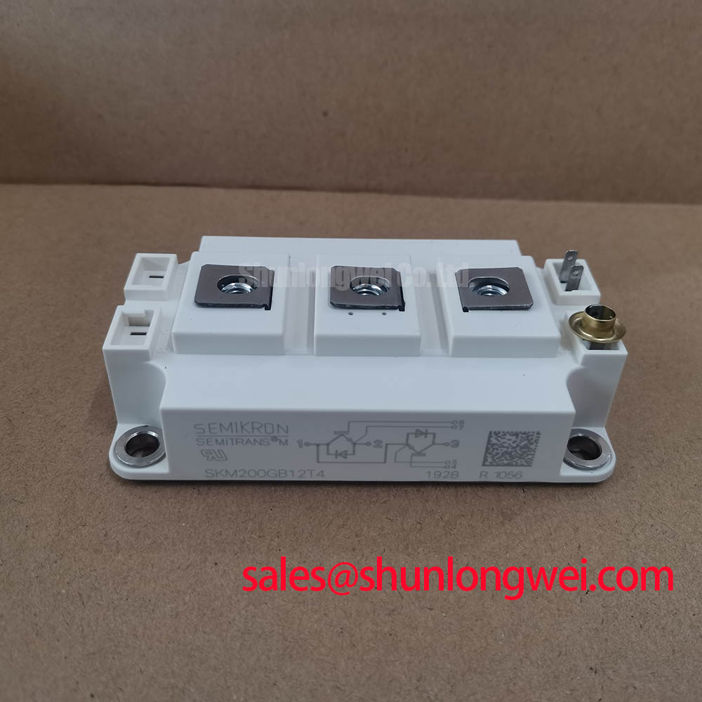
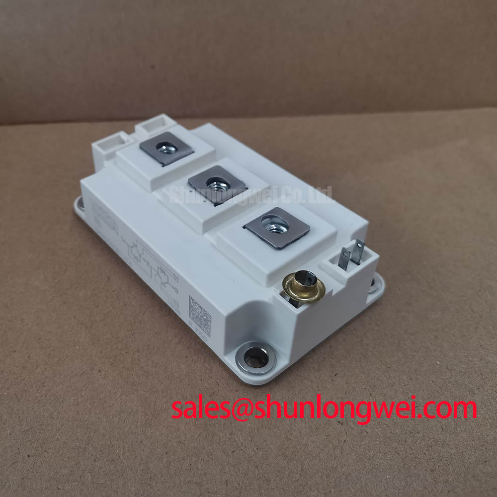
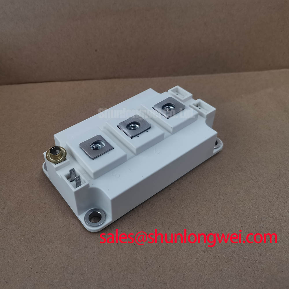
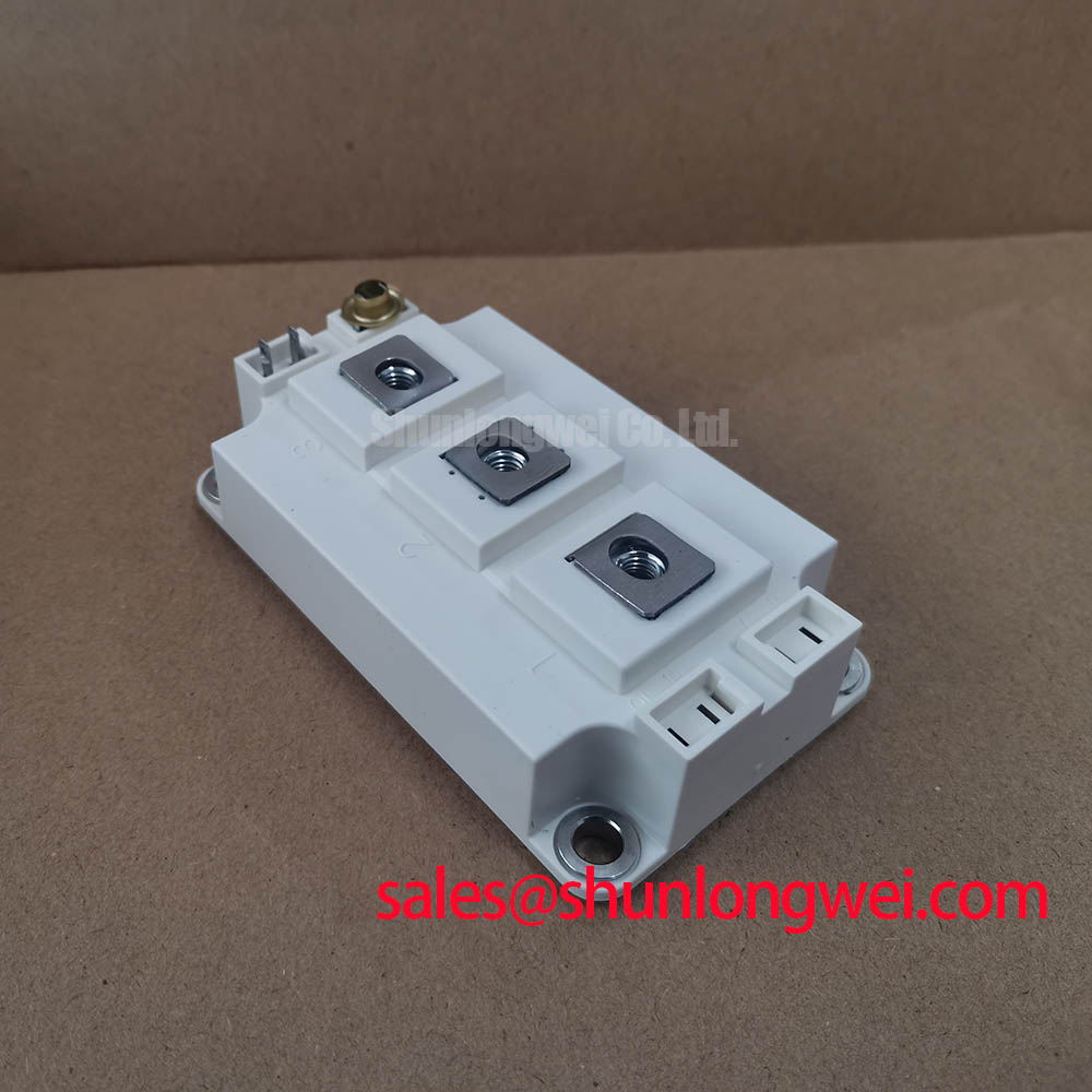
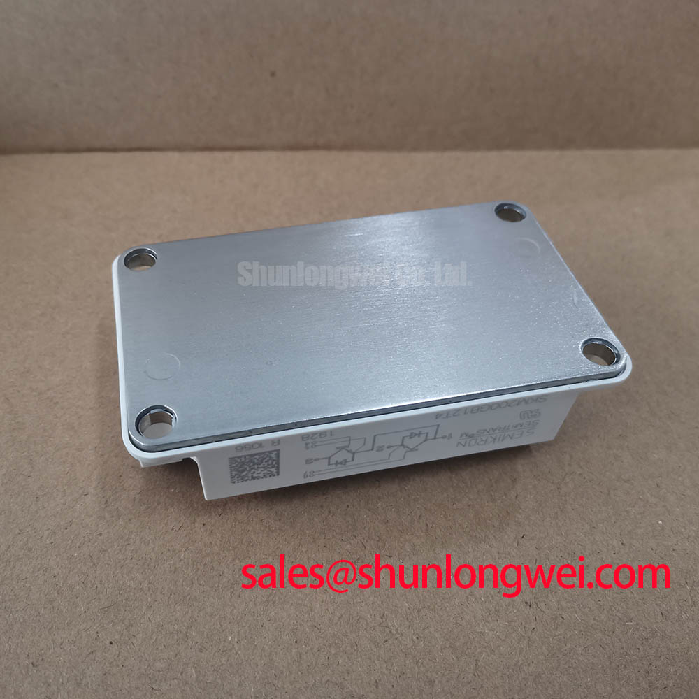
The Semikron SKM200GB12T4 is a half-bridge IGBT module featuring Trench IGBT4 technology and integrated CAL4 freewheeling diodes. This module is optimized for high-power switching applications requiring high thermal efficiency and low conduction losses.
- Core Ratings: 1200V Collector-Emitter Voltage | 200A Continuous Collector Current (at Tc = 80°C) | Typical VCE(sat) of 1.85V.
- Key Advantages: Lower conduction losses minimize cooling requirements. Robust short-circuit withstand time simplifies gate driver protection design.
- Design Integration: Direct Bonded Copper (DBC) baseplate isolation solves transient thermal management challenges in compact enclosures.
Download Official Datasheet (PDF)

Technical Analysis and Engineering Value
By employing a trench gate structure, the SKM200GB12T4 significantly reduces on-state voltage drops compared to older planar structures. The typical saturation voltage of 1.85V at rated current limits conduction losses, which directly improves system conversion efficiency. Engineers can read more about these structural changes in our guide on trench gate evolution and VCE(sat) optimization.
The integration of the CAL4 soft-recovery diode mitigates high-frequency voltage spikes during switching intervals. This soft-switching behavior reduces both switching losses and electromagnetic interference. To understand why matching the diode behavior is critical to overall module reliability, see our technical review on how soft recovery diodes dictate system performance.
Thermal management is supported by an isolated copper baseplate. You can visualize thermal resistance as the diameter of a drainage pipe. A lower thermal resistance represents a wider pipe, allowing heat to escape faster from the silicon junction to the heatsink. This layout minimizes thermal stress. For a deeper look at packaging insulation, refer to our analysis on isolated baseplates and high voltage module safety.
Optimized Application Scenarios
- AC Motor Drives (VFDs): High switching capability and soft-recovery diodes handle inductive motor loads reliably.
- Solar Inverters: Low saturation voltage improves daily energy yield in grid-tied solar conversion stages.
- Uninterruptible Power Supplies (UPS): Half-bridge topology allows compact implementation of inverter output stages.
- Induction Heating: Trench gate characteristics support high switching frequencies with low thermal dissipation.
Best match: High-efficiency AC motor drives and solar inverters requiring compact half-bridge configurations with low conduction losses.
Key Specifications Parameter Table
| Parameter Group | Symbol / Parameter | Conditions / Value | Unit |
|---|---|---|---|
| Absolute Maximum Ratings | VCES (Collector-Emitter Voltage) | Tj = 25°C / 1200 | V |
| IC (Continuous Collector Current) | Tc = 80°C / 200 | A | |
| Electrical Characteristics | VCE(sat) (Saturation Voltage) | IC = 200A, Tj = 25°C / 1.85 (typ.) | V |
| tpsc (Short Circuit Withstand Time) | VCC = 800V, VGE ≤ 15V, Tj = 150°C / 10 | μs | |
| Thermal & Isolation Characteristics | Rth(j-c) (Thermal Resistance Junction-Case) | Per IGBT / 0.16 (max.) | K/W |
| Visol (Isolation Voltage) | AC 50Hz, 1 min / 2500 | V |
Engineer FAQ
What negative gate voltage is recommended for turn-off bias?
To prevent parasitic turn-on due to collector-emitter transient voltages (dv/dt), a negative gate voltage of -7V to -15V is recommended. For more details on gate-drive configurations, see our guide on gate noise immunity and negative voltage biasing.
How should the transient thermal impedance (Zth) curves be used for transient overload calculations?
The transient thermal impedance curves in the datasheet allow engineers to calculate the junction temperature during short duty-cycle overload pulses. The junction temperature must never exceed the absolute maximum limit of 175°C.
What is the maximum torque allowed for mounting terminals?
The recommended mounting torque for the electrical terminals is 2.5 to 5 Nm, and 3 to 5 Nm for the heatsink mounting. Under-tightening increases electrical and thermal contact resistance, while over-tightening risks physical damage to the module package.
Closing Statement
The Semikron SKM200GB12T4 provides a balance between low saturation voltage and high switching ruggedness. It serves as a dependable building block for high-efficiency inverters, helping developers achieve optimized thermal designs in compact industrial configurations.