Designs requiring space-grade components must take into account the variances in component values that can occur over time. This is especially true for resistors, which can exhibit significant changes over their lifetime. Unfortunately, while most public guidelines for estimating Resistor aging are reasonably conservative, the issue is designers are following typical data and advertising hype and not the actual limits that vendors are allowed to deliver to.
Given there aren’t too many suppliers of space-grade resistors, and that MIL-PRF-55342 establishes specifications for resistors, the variance that different companies use in the aging tolerances and guidelines for resistors is quite surprising. Over the years, in the WCCA we have performed, we have seen everything from 0.1% to 4% for the aging/combined environments tolerance term, often referred to as just aging. Reconsider using 0.5%, or even 1%, for MIL-PRF-55342 resistor end-of-life effects; it is probably not supportable.
The initial and temperature tolerances (beginning-of-life, or BOL) are always well defined in the datasheet. The radiation tolerance is zero for passive components. This leaves only the aging tolerance to be defined as the end-of-life (EOL) variance. This is where programs and analysts tend to get creative.

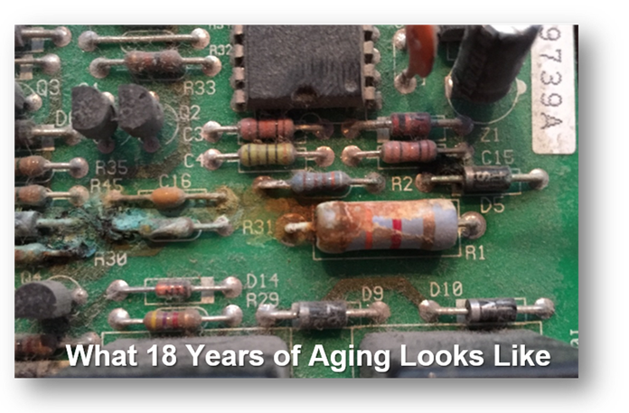
Fig 1: This photo shows what 18 years of resistor aging can look like in air. (Image: AEi Systems)
Currently, our customers are using anywhere from 0.24% to 1.25% for Class A space missions with many critical programs opting for 0.5% aging for a 10-year mission. This is apart from the initial and temperature tolerances and just covering the end-of-life variance. These variations in expectation are normal and understandable since the materials utilized for the resistive film vary substantially and have correspondingly different properties. Therefore, any single data source selected would have limited applicability.
Let’s evaluate whether these numbers seem reasonable, or at least reasonably-conservative for a worst-case circuit analysis (WCCA).
The part tolerance database, often referred to as the PVDB (parts variability database) is at the heart of the worst case analysis. Touch the PVDB after analysis is started, or make a mistake, and the entire analysis could be impacted. This would certainly be the case for any resistor tolerance changes. This is one of the main reasons why the PVDB is largely developed at the beginning of the WCCA, and why customer/program approval is crucial. Without sign-off from all parties reviewing the WCCA, calculations should not begin.
I discussed the level of rigor needed for a WCCA in my blog WCCA: Lack of rigor will cost you, but clearly the most impactful EOL tolerances are that of the resistors. In my recent papers on the test vs. analysis budget ratio (References 1 and 2), I discussed total BOL vs. total EOL variance ratios of various components. Resistors are certainly the most impactful and can have the largest EOL change percentage-wise, as shown in the table below.

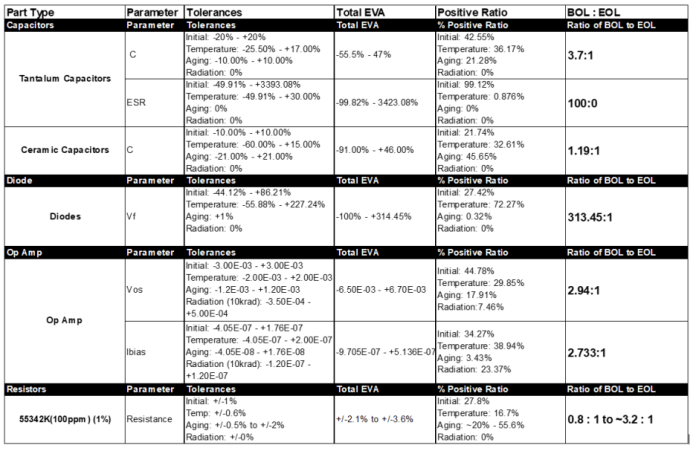
Fig. 2: Don’t pare down to the bone unless you know where the bone is (tolerance-wise). (Image: AEi Systems)
This table shows the BOL to EOL tolerance stack-up variance for several different types of parts.
The extreme value tolerance variation for each part used in the WCCA is the algebraically summed combination of the initial, temperature, combined environments/aging, and radiation tolerances. The aging tolerance is usually extrapolated from Arrhenius equations based on burn-in, or short- or long- term life test data (Reference 3). A sample calculation is shown in Fig. 3. If test data is not available, then public or proprietary guidelines are used as assumptions (Fig. 4).

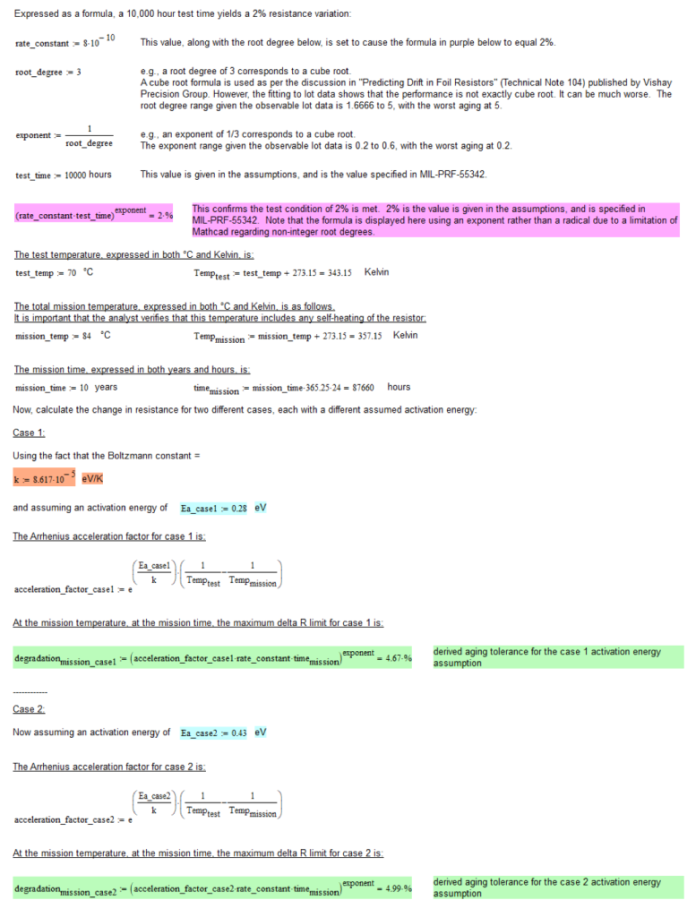
Fig. 3: This sample calculation of the resistor aging is based on burn-in/life test data for an 84°C 10-year mission. For a 70°C, 10,000-hour, 2% life test limit (as per the military specification [Reference 10]), the aging is between 4.67% and 4.99% using Ea as 0.28 or 0.43eV. 0.28eV is suggested by ESA (Reference 4). It should be noted that the activation energy Ea, a critical element of the calculation, is not actually known with certainty. (Image: AEi Systems)
Component aging is a continuous process of physicochemical change. It is generally assumed that aging may take place even if the part is unbiased. That means you not only need to account for the mission lifetime, but you also need to add in storage, integration, and test time at the appropriate temperature conditions – unless, of course, you store your parts in nitrogen or some other inert environment.
Surprisingly, resistive product vendor State of the Art, Inc. (SOTA) states that resistors may be up to 10 years old when shipped. However, SOTA does not believe that thin film resistors age unpowered: “SOTA stores devices in standard atmosphere (no N2 purge) at typical ~23°C ambient temperature for up to 10 years without observed degradation.”
SOTA purges stock after 10 years from manufacturing to ensure minimal construction and materials variation within stock. They have no evidence of room temperature storage resulting in a change in lot test behavior: “T-level screenings are typically provided on existing lots from stock. The T-level screening provides Group A with power conditioning, Group B inspections, and is represented in the ER Life. No issues have been identified that are associated with aging. For the few examples of the original lot and T-level lot being represented in ER Life, there is little difference to no difference in performance.”

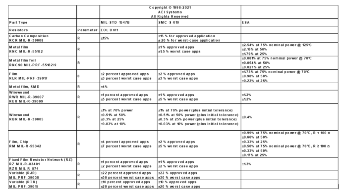
Fig. 4: This table shows the typical public guidelines for resistor aging tolerances. (Image: AEi Systems)
A long list of manufacturing and test-related tolerances, as defined in the military specifications, determines the combined environmental tolerance. The manufacturing-related tolerances are different for each program and tailored to the manufacturing, test, and qualification requirements of each program. While they are related to manufacturing and test, they are often lumped in with aging as EOL factors. These military specification tolerances are not to be dismissed and can, as noted in Fig. 5, easily rival the aging (time-based) tolerance.

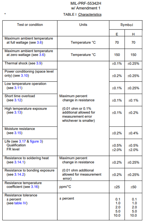
Fig. 5: The specification for MIL-PRF-55342 resistors indicates a variety of manufacturing and test related tolerances that can add up. Ultimately, manufacturers can deliver resistors that meet a life test requirement of less than or equal to 2.0% change in resistance over the 10,000 hours at 70°C (Reference 10).
What the vendor-provided aging data shows
To reduce assumptions used in WCCA and the uncertainty in program/vendor claims, we contacted SOTA and Vishay last year; this section covers the summary of the conversations and data exchanges.
We did some work with SOTA about a decade ago and wrote a paper on it (Reference 5). When contacted this time, SOTA sent us the same document they initially sent to us in 2009. We pursued further and SOTA came through, providing 10,000- and 100,000-hour lot data. We were grateful to say the least.
The data contained in the SOTA life test performance document paints a rosy picture and clarifies several assumptions that have been made in the past. The data in ‘180502TN1206Life.pdf’ (Reference 6) contained 166 lots of 10,000-hour life test data for 1206 thin film resistors (characteristic E, termination B, 70°C). They consisted of various resistor values (milliohms to 1 MW) measured under MIL-PRF-55342 conditions (method paragraph 4.8.11). Two lots of data are shown in Fig. 6.

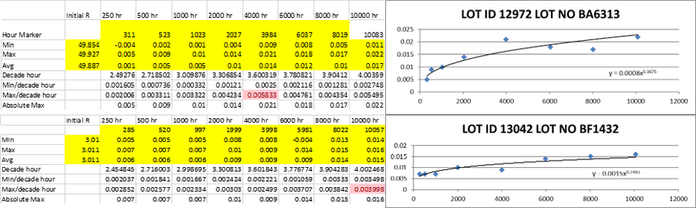
Fig. 6: Two of the 70°C 10,000 life test data lots provided by SOTA along with various measurement calculations are shown to the left. The data was fit to a cube root function (approximately) on the right. The Y axis is % change in the resistor value, the X axis is time in hours, and large value jumps are noted in red. All 166 lots were similarly analyzed. (Image: AEi Systems)
Each lot is fit with an expression that has a constant and exponent. For instance, 0.0015x0.2483 or 0.0008x0.3675, as shown in Fig. 5. The formula is then extended to 87660 hours to find the total aging variation.
The values in red in Fig. 5 are the largest per decade hour rates for the lot. The per decade hour rates are computed from the initial reading to the hour at the top of the column (the 250 hour rate is from 0 to 250 hours, the 500 hour rate is from 0 to 500 hours, and so on).
As hinted at in SOTA and Vishay datasheets (Fig. 7), the resistors do indeed fit a cube root function, though the exponent varies widely. This revelation alone will likely result in the changing of some proprietary guidelines that are used by prime aerospace manufacturers.

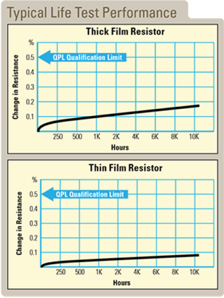
Fig. 7: Resistor data sheets hint at cube root aging for resistors. (Source: State of the Art, Inc.)
Summarizing the data presented in the SOTA ‘180502TN1206Life.pdf’ 10,000 hours lot set:
- Thin film 1206 chip resistor aging follows a cube root function with an exponent that varies from 0.2 to 6. This means that the aging can be significantly worse than the simple cube root estimate.
- The measurement process has errors. The magnitude of the error is unknown but is usually accompanied by measurement “jumps.”
- It is assumed that if there is a large jump in error over a short period of time (> 0.5% for < 2000 hours) that the resulting data point is suspect.
- Errors < 0.01% are indistinguishable from measurement error. Depending on the long term accuracy and value range error, it is not inconceivable to have a measurement error of up to 0.02%. Changes > 0.02% that recover to be in-line with measurement prior to the excursion are due to measurement error.
- The level of power stress is another variable not factored into the data; however, life test data is at full rated power, not to exceed rated voltage, as per MIL-PRF-55342.
- Vishay has not provided raw data to date, so it is not known if their performance meets the cube root aging as their application note indicates.
- The data provided was for thin film resistors that consist of films of metal alloys or metal oxides, whereas thick film resistors consist of glass-metal frits that typically age at a greater rate than do the thin films (Fig. 6).
- The trend is overwhelmingly and always positive. This means that the tolerance should likely not be random but biased. This will impact your WCCA calculations if EOL tolerances are RSS’d because resistance aging variations would only be in one direction.
Brian Hill, thin film manager at SOTA noted, “Based on the limited long term data sets (100k+ hours), I believe the general trend is a slow drift positive over time. I suspect measurement error provides the observed wobble around this average (almost linear) positive behavior. Data may suggest an initial higher rate in the first 250-500 hours of test before achieving a more steady-state behavior, but in thin film this is harder to determine due to the change being so close to measurement error boundaries.”
The data closely mimics ESA data from ECSS-Q-60-11A (Reference 7). The graphs also have the added benefit of showing the variation with stress. The ESA curves in Fig. 7 do not follow the SOTA data exactly, and at higher power levels, the ESA calculations might indicate cause for concern with a single program-wide aging assumption.

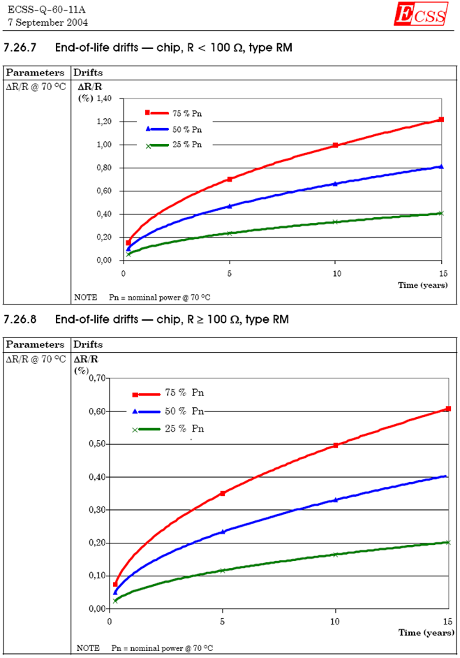
Fig. 8: ESA is one of the only sources of data on the change in aging with stress levels. ESA specifically, and SOTA qualitatively, indicate a strong influence of power stress on the resistor aging (slope of the time variation). The underlying data that produced this graph was NOT available. Source: ECSS-Q-60-11A: 55342 resistor aging. (Image: AEi Systems)
The bottom line
The SOTA data set was assessed. The 10k hour data was extrapolated to 87,660 hours using the equation that was fit using the 10k hour data. The resulting 87.66k hour deviations are summarized in Figs 9 & 10.
For the data set reviewed, and disregarding lots with aging of greater than ~2%, 81% of the lots were less than 0.065% aging for 10 years at 70°C and 19% of the lots were between 0.065% and 0.395%. At 84°C, assuming an Ea of 0.28, 82% of the lots were less than 0.065% aging for 10 years and 18% of the lots were between 0.065% and 0.425%. The actual drift depends on the properties of the system resistor lot, so other vendors, who have different formulas for resistor composition, may not adhere to these trends.

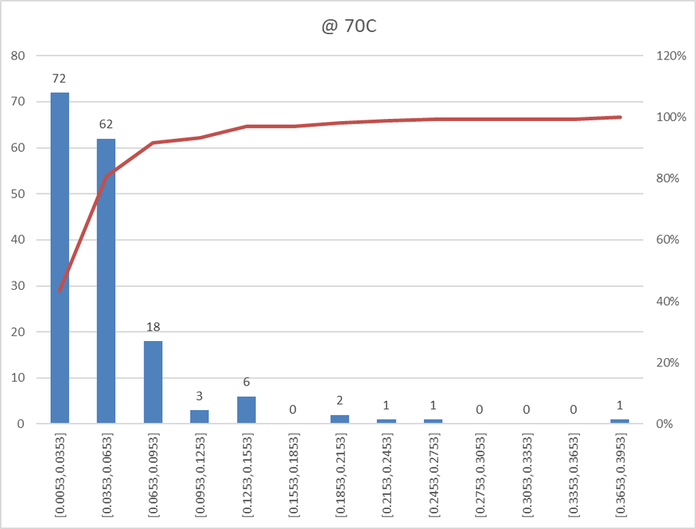
Fig. 9: 166 lots of 10,000-hour test data was extrapolated to 87,660 hours at 70°C. (Image: AEi Systems)
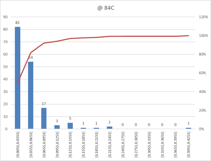
Fig. 10: 166 lots of 10k hour test data was extrapolated to 87.66k hours at 84°C using an Ea of 0.28eV. (Image: AEi Systems)
You will also need to account for your program’s worst-case temperature. Even with qualification temperatures in the 60°C-65°C range, temperature rises due to power dissipation can increase a resistor’s average temperature 10-20 degrees above the ambient environment and may create a resistor hot spot with an even higher localized temperature. These hot spots may drive resistance aging.
For temperatures > 70°C, the aging tolerances are worse. The variation with temperature is related to the activation energy, Ea. The Ea is not known for thick and thin metal film resistors from various manufacturers. ESA suggests an Ea of 0.28eV. The military specification indicates Ea can be lower, though common values are between 0.28eV and 0.43eV. Therefore, translation of this data requires an Ea assumption. For comparative purposes, 84°C is arbitrarily used in Fig. 9.
The bottom line is this. Unless you are buying an entire lot of resistors or you have written a source control document (SCD) to bound the life test performance, the lot data is irrelevant. Yes, it indicates better than specification performance. This has been claimed for years by various manufacturers, but regardless, as per the military specification, the vendor can still provide you with resistors that only meet 2% at 10k hours at 70°C.
It is, therefore, possible assuming a nominal-case cube root exponent (0.333) and Ea value (0.28) that a 2% 10k hour variance can be as high as 4.67% (Reference 8)! The aging tolerance gets much worse when the maximum cube root (exponent) variance from the lot test data is used (as high as 0.6). Additionally, this is without any adjustments for resistor stress. And whether you use the specification or somehow believe you can rely on lot data; you must still contend with other manufacturing/test tolerances which are not 0%.
Therefore, it is not reasonable to use 1%, let alone 0.5%, for MIL-PRF-55342 resistor aging for a 70°C 10-year mission.
To create a SCD that would bound the EOL aging tolerance to 0.5% at 10 years 84°C, you could request a 10k hour test limit of 0.215% (exponent=0.3333, Ea=0.28eV) (Reference 8). SOTA notes that providing resistors to a 10,000 hour life test requirement is expensive and has long lead times (manufacturing + 14 month test lead time). Most people are making this assessment based on 1000- or 2000-hour life test data (manufacturing + 1.5 to 3 months test lead time).
Special thanks to Brian Hill at SOTA and Michael J Cozzolino at Aerospace Corporation for their comments and guidance.
References
- Optimizing Electronics Test/Analysis Ratio, Charles Hymowitz, Feb. 7, 2020.
- Test vs. Analysis; What’s the right ratio for achieving high reliability?, Charles Hymowitz, PSMA Webinar, Thursday, February 18, 2021.
- Arrhenius Equation, ScienceDirect
- ECSS-Q-TM-30-12A, End-of-life parameter drifts – EEE components, October 2010 on page 46
- Why Your 1% Resistor Really Isn’t? Resistor Tolerance Study, Steve Sandler, Charles Hymowitz, Space Power 2009, Aerospace Space Power Workshop
- Life Test Performance, Resistive Products, State of the Art, Inc., 180502TN1206Life.pdf
Main SOTA thin film life test data file used in the compilation of 180502TN1206Life_Macro with additions PH 10khr.xlsm – 180502TN1206Life_Macro with additions PH 10khr.xlsm – extrapolation to 10Yr Tol 70C Full Power based on SOTA 10khour test data – Other life test data files including some with 100k hours! - ECSS-Q-60-11A 7 September 2004 Derating and end-of-life parameter drifts — EEE components
- Thin Film Aging Tolerance w Variable Root 10000 hours.xmcd’ Mathcad file, contact me if you would like a copy.
- SMC-S-010_12APR2013, Space and Missile Systems Center Standard Technical Requirements for Electronic Parts, Materials, And Processes Used in Space Vehicles, SMC Standard, April 12, 2013
- MIL-PRF-55342 Rev H, Performance Specification Resistors, Chip, Fixed, Film, Non-established Reliability, Established Reliability, Space Level
This article originally published at sister publication EDN.
about AEi Systems