
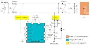
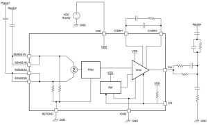
In principal, the ICs implement a capacitance multiplier circuit to emulate the Y-Capacitors in a conventional passive filter design.
They do while sitting amongst smaller filter inductors and capacitors (top diagram) while summing the high-frequency components of the voltages from the two or four ac power conductors, and then injecting an anti-phase ac current derived from these signals back into the neutral.

“The effective active capacitance is set by the circuit gain and the injection capacitance,” according to TI. “The active EMC filter sensing and injection impedances use relatively low capacitance values with small component
footprints.”
[Scroll down to the bottom of this article for a discussion on where exactly currents flow in this scheme]


The sense and injection capacitors (see diagrams) have to be Y-rated components.
The other passive components on the output are for damping – to manage resonance between the still-needed common-mode choke inductance and the injection capacitance – which appear in the active loop gain as a pair of complex zeros.
There are four devices: TPSF12C1 and TPSF12C3 for single- and three-phase commercial applications, then TPSF12C1-Q1 and TPSF12C3-Q1 for automotive use. Volume production is scheduled for the second quarter of 2023, with additional active EMI filter ICs appearing later this year.
Operation is over 8 to 16V (18V withstood) and up 105°C ambient (150°C junction).
Protections include under-voltage lock-out, and thermal shut-down, and there is an enable pad.
They “meet IEC 61000-4-5 surge immunity requirements, minimising the need for external protection components such as transient voltage suppression diodes”, said TI.
Packaging is 4.2 x 3.3mm 14pad SOT-23
Applications are foreseen in on-board chargers, servers and uninterruptable power supplies.
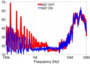
This application note has the clearest information about these ICs and includes an example of Inductor size reduction
Electronics Weekly ponders how this scheme works (Please read TI response immediately below this, saying that this pondering is wrong, although not explaining where the injected current loops are. Just in case it is a problem of nomenclature, further questions have been sent regarding current loops associated with the injected current).
EW’s pondering:
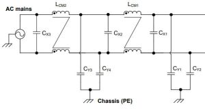
TIs literature mentions injecting current into the neutral line a great deal, but not, it appears to Electronics Weekly, that the ground terminal (and Vdd+decoupling) of the IC is doing the bulk of the work. The IC’s ground is connected to EMC ground, and common-mode EMC energy is dumped through here, just as it would be with normal Y-capacitors – but the gain in the circuit decreases the necessary capacitor size.
The Y-capacitors in a passive design are replaced by the gain plus CINJ and a path through the existing X-capacitors – in effect, the IC and its circuit have converted some of the common-mode noise into differential noise that can be dealt with by the X-capacitors. In a neutral-less three phase system, CINJ would need to be replaced with a star of three capacitors.
EW question: Is the common-mode noise being removed by injecting ac current in to the ground through the IC’s ground connection pin?
TI response: No, an AC current is injected into the power lines that is equal in amplitude but opposite in phase to cancel out the CM noise.
EW question: If so, and if this current is relative to the neutral line: Is this circuit turning some of the suppressed common mode noise into differential noise – which is still present on the non-neutral power line (or lines, in three phase)
TI response: No, the CM noise is not being converted into DM noise. DM noise may still exist in the power lines, but CM noise is specifically reduced by the AEF. CM noise dominates at the lower frequencies through the contribution of the parasitic capacitances of the system and is mainly responsible for large filter size.