
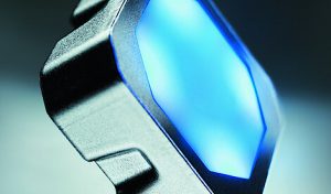
Called the ‘CHS’ range, they come in three versions: non-illuminated, illuminated and sealed illuminated.
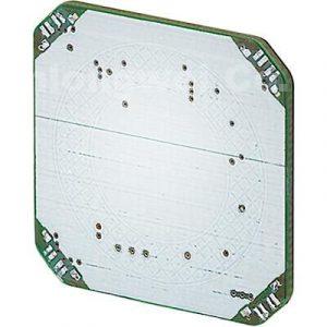
They are mounted by gluing them to the back of the panel with 3M 468MP tape.
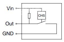

CHS 1 circuit – output is an open collector
“The CHS is programmed as standard so that it does not trip in the event of field changes caused by liquids or minor wiping contact. This is only done by precise touching of the switching surface,” according to the company. “However, adjustments can be made here at the customer’s request. This applies in particular to the thickness of the material behind which the switch is bonded. As standard, the sensitivity is designed for a glass thickness of up to 2mm.”

They are:
- CHS 1 – no illumination (right)
30mA 70Vac* 100Vdc open collector output
27.7 x 27.7 x 8.5mm to rear of mated connector - CHS 2 – RGB illumination
100mA 42Vac 60Vdc isolated mosfet output
30 x 30 x 10.8mm - CHS 3 – RGB illumination (top)
2A 40Vac 60Vdc isolated mosfet output
potted for harsh environments
30 x 30 x 12.4
Cables exit rearwards and add to depth.
CHS 3 has flying leads, while the other two have connectors.
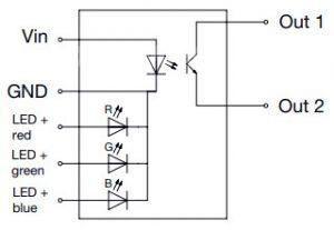

Operation is over -40 to 85°C, and across 5 to 28Vdc for the capacitive sensor. Current through the LEDs needs to be controlled by the external circuit – see block diagrams.
Ignoring any illumination, consumption is <1mA at idle and <6mA when actuated.
The CHS product page is here and the data sheet here – diagrams and *contact ratings above are taken form the ‘27.10.2021’ data sheet