“Early transmitters mostly used LC oscillators, and the frequency drift was more serious. The emergence of SAW devices has solved this problem. Its frequency stability is roughly the same as that of crystal oscillators, and its fundamental frequency can reach several hundred megahertz or even gigahertz. There is no need for frequency multiplication, and the circuit is extremely simple compared with crystal oscillators.
“
Although the performance of OOK modulation is poor, its circuit is simple and easy to implement, and its work is stable. Therefore, it has been widely used. It is almost invariably used in automobile and motorcycle alarms, warehouse gates, and home security systems. Circuit.
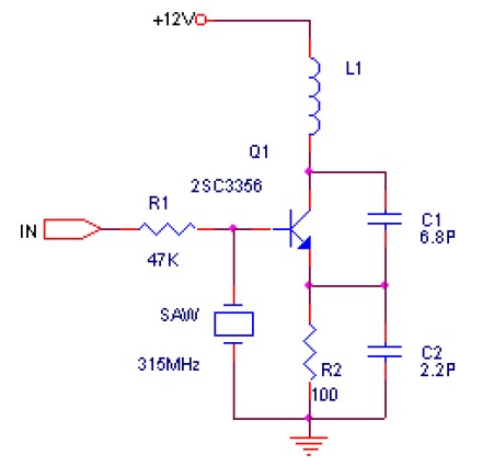
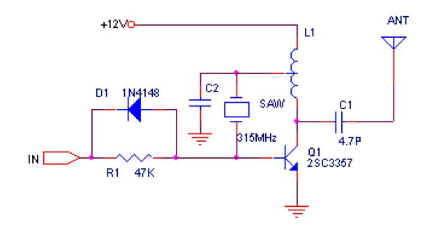
Early transmitters mostly used LC oscillators, and the frequency drift was more serious. The emergence of SAW devices has solved this problem. Its frequency stability is roughly the same as that of crystal oscillators, and its fundamental frequency can reach several hundred megahertz or even gigahertz. There is no need for frequency multiplication, and the circuit is extremely simple compared with crystal oscillators. The following two circuits are common transmitter circuits. Due to the use of SAW devices, the circuit works very stably. Even if the antenna, SAW or other parts of the circuit are grasped by hand, the transmitting frequency will not drift. Compared with Figure 1, the transmit power of Figure 2 is higher. It can reach more than 200 meters.


The receiver can use super regenerative circuit or super heterodyne circuit. The cost of super regenerative circuit is low, and the power consumption is as small as about 100uA. The superheterodyne receiver in the mid-stage amplifier is similar. However, the super regenerative circuit has poor working stability and poor selectivity, which reduces the anti-interference ability.
The following figure shows a typical super-regenerative receiving circuit.
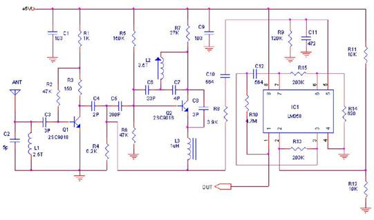

Typical super regenerative receiving circuit
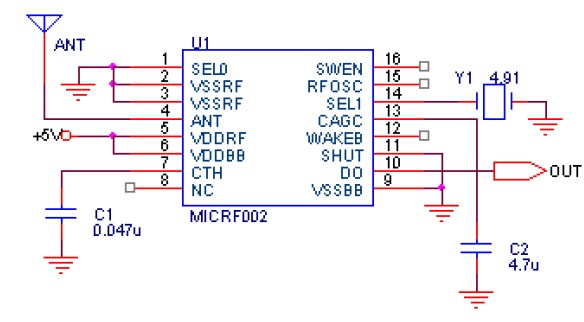
The sensitivity and selectivity of the superheterodyne circuit can be done very well. The single chip introduced by the American Micrel company can complete the reception and demodulation. Its MICRF002 is an improved type of MICRF001. Compared with MICRF001, it has lower power consumption and has Power off the control terminal. MICRF002 has stable performance and is very simple to use. Compared with the ultra-reproduction circuit, the disadvantage is the high cost (RMB35). The following is its pin arrangement and recommended circuit.


ICRF002 uses a ceramic resonator instead of a different resonator, and the receiving frequency can cover 300-440MHz.
MICRF002 has two working modes: scanning mode and fixed mode. The scanning mode accepts bandwidth up to several hundred KHz. This mode is mainly used with LC oscillating transmitters because the frequency drift of LC transmitters is relatively large. In scanning mode, the data communication rate is 2.5KBytes per second. The bandwidth of the fixed mode is only tens of KHz. This mode is used to match the transmitter that uses the crystal oscillator to stabilize the frequency, and the data rate can reach 10KBytes per second. The working mode selection is realized through the 16th pin (SWEN) of MICRF002. In addition, using the wake-up function can wake up the decoder or CPU to greatly reduce power consumption.
MICRF002 is a complete single-chip superheterodyne receiving circuit, which basically realizes the “direct output of data” after the “antenna input”, and the receiving distance is generally 200 meters.


There are many types of wireless transmission circuits that use SAW resonators. Here is another circuit. This circuit was made by combining the actual samples of the module introduced in the article after referring to the article in the Electronic newspaper 3 years ago. After mass production, some parameters have been improved, and now this product is really good. But now there are too many imitation products of Dongdong, and the quality is very different, but because it is relatively simple, I think it is necessary to show it to everyone. I also found many similar circuit diagrams on the Internet, but Some of them have pitfalls. I hope everyone should pay attention to learn to identify some bugs by themselves. For this module, I have not tested the jue pair power of its wireless transmission, but we drove the car over the distance on the road. It can reach a distance of 800 meters with the normal 315M super-regenerative receiver module. As long as the circuit reduces the value of the 8050 base resistance, the communication distance will increase to 1200 meters or even farther, but after a lot of experiments, it is proved that it is not very reliable. The reason is not very clear to me. There may be two reasons. One is that when R2 is small, the 8050 has a slight turn-on, which causes the launch to not be cut off quickly. Another is that R2 is very small, and the 8050 turn-on current is relatively large, which may be a disturbance to the power supply and fail to meet the vibration requirements. I once doubted whether my circuit is very matched, so I bought a lot of similar modules that claim to be 1500 meters, and found that they also have the same unreliability, generally showing that they occasionally fail to vibrate or the baud rate is less than 2K. Later, I increased the R2 Resistor. When it was greater than 15K, the emission was always normal, and the distance was almost the same as that of 27K, so now I use this resistor. For L1L2 here, I use a 0.8mm drill bit that eliminates the enameled wire in 3mm. It is a semi-born product with 4 rounds of upper winding. During the production, there may still be some problems with the PCB wiring. I remind everyone that the wiring should be as simple as possible, and the wiring should be as short as possible. The components should be selected. The PCB board can be 1.5 mm thick.
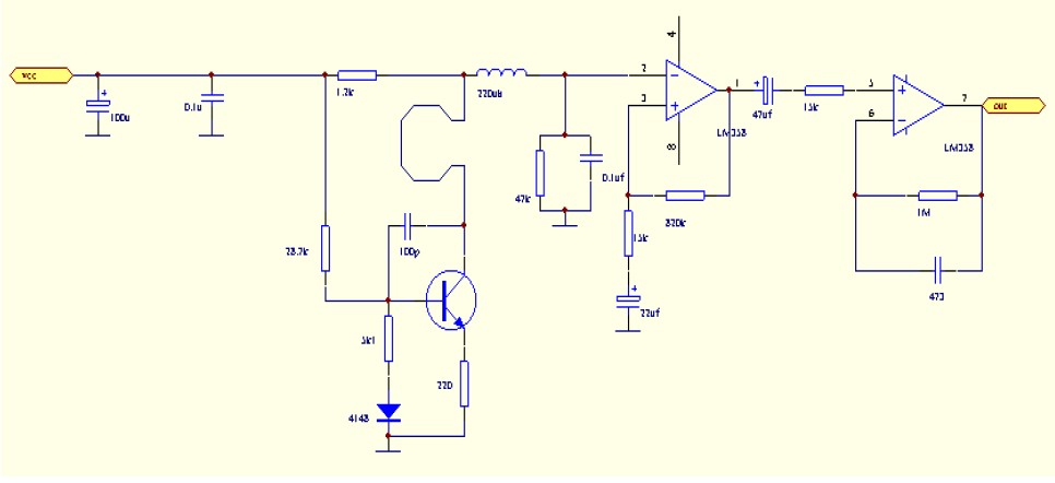

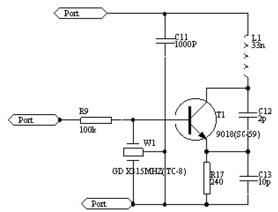
Super regenerative receiving circuit. People always say that compared with super heterodyne, what’s wrong with it, bandwidth, anti-interference ability, bad radiation, as if it’s not good at anything. , Then I can tell you very clearly that most of the wireless receiving circuits used in anti-theft alarms on the market now use super-regenerative circuits. Almost all remote control toys use that stuff, so Well, its market is quite large, because its sensitivity is not comparable to that of superheterodyne, and debugging is simpler than superheterodyne. Many friends may have noticed that the high frequency and small inductors I use here seem to be PCBs. Why? The key is to be easy to do. Although I did a lot of experimental work when I did it, once it was confirmed, it was relatively stable. The following is a brief introduction to the circuit. The loop in the front is the PCB Inductor, and the adjustable capacitor at the back is used for tuning. The tuning method is to face the spectrum analyzer and adjust the local oscillator signal to the 315MHZ you want. If there is no spectrum analyzer If it is, then it is directed to the transmitter and slowly gathers it until it can be received. The weak data signal is input from the PCB inductance through the 10K resistor and 10UF capacitor to the base of T2. After preliminary amplification, it enters the LM358 to continue the shaping and amplification. The amplified digital signal is directly input to the signal input pin 14 of the PT2272 for decoding, and the decoded output pin is the 10-13 pin of the PT2272.
The radio remote control transmitter T630 is a miniature transmitter with a built-in wire and no signal. Its transmission frequency is 265MHz. When powered by a 12V power supply, the remote control distance is 100M, the working current is only 4mA, and its volume is 28X12X10mm.
The radio receiver T631, a built-in antenna, is a receiver and demodulator like a TV tuner. Its typical working voltage is 6V, standby working current is 1mA, receiving frequency is 265MHz, and its volume is only 31X23X10mm. They can be used to easily produce various radio remote control devices, which have the advantages of miniaturization, long transmission distance, low power consumption, and strong anti-interference ability. It can easily replace infrared, ultrasonic transmitter and receiver.
The circuit principle of the radio head T630 is shown in the figure. Circuit four transmitting tube V1 and peripheral components C1, C2, L1, L2, etc. constitute an ultra-high frequency transmitting circuit with a frequency of 265MHz, which is launched into the air through the loop antenna L2. Antenna L2 uses silver-plated wire or enameled wire with a diameter of 1.5mm, and the antenna size is 24mm (length) X 9mm (height). The triode V1 selects the high-frequency launch tube BE414 or 2SC3355.
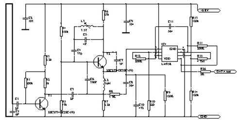
The circuit principle of the radio remote control receiver T631 is shown in the figure. The receiving circuit is mainly composed of V1, IC, etc. V1 and C7, C9, L2 and other components form an ultra-high frequency receiving circuit. Fine-tune C9 to change its receiving frequency so that it is strictly aligned with the 265MHz transmitting frequency. When the antenna L2 receives the modulated wave, it is tuned by V1 to amplify the low frequency components, and then pre-amplified by V2 and sent to the IC LM358. After further amplification and shaping, it is output by the 7th pin of the LM358. The actual size of the printing is 31mmX23CC, and the antenna size is 27mm (length) X9mm (height). OUT is the signal output terminal, and the Transistor V1 selects BE415 or 2SC3355.
The capacitor C9 can be a small adjustable capacitor. IC chooses LM358.
In order to reduce the volume in the transmitting and receiving circuit, all the resistors are 1/8W or 1/16W metal film resistors; the electrolytic Capacitors are also ultra-small capacitors, and the other capacitors are all high-frequency ceramic capacitors. When soldering, the component pins should be cut as short as possible to make it close to the circuit board. The circuit board material should be a high-frequency circuit board.
The following are two-carrier transceivers that use surface acoustics. Compared with the circuits described above, they have a longer transmission distance, stronger anti-interference ability, and easier production and debugging.
Launch part


Receiving part

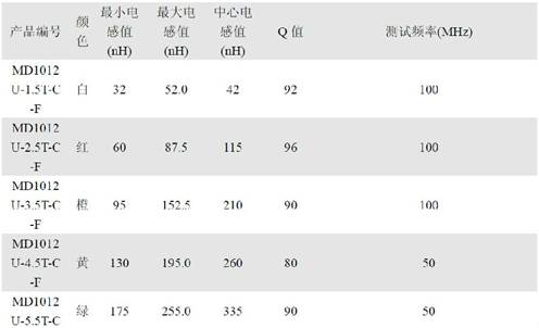
To add a bit of content, about the inductance in the circuit:


Although the performance of OOK modulation is poor, its circuit is simple and easy to implement, and its work is stable. Therefore, it has been widely used. It is almost invariably used in automobile and motorcycle alarms, warehouse gates, and home security systems. Circuit.
Early transmitters mostly used LC oscillators, and the frequency drift was more serious. The emergence of SAW devices has solved this problem. Its frequency stability is roughly the same as that of crystal oscillators, and its fundamental frequency can reach several hundred megahertz or even gigahertz. There is no need for frequency multiplication, and the circuit is extremely simple compared with crystal oscillators. The following two circuits are common transmitter circuits. Due to the use of SAW devices, the circuit works very stably. Even if the antenna, SAW or other parts of the circuit are grasped by hand, the transmitting frequency will not drift. Compared with Figure 1, the transmit power of Figure 2 is higher. It can reach more than 200 meters.


The receiver can use super regenerative circuit or super heterodyne circuit. The cost of super regenerative circuit is low, and the power consumption is as small as about 100uA. The superheterodyne receiver in the mid-stage amplifier is similar. However, the super regenerative circuit has poor working stability and poor selectivity, which reduces the anti-interference ability.
The following figure shows a typical super-regenerative receiving circuit.

Typical super regenerative receiving circuit
The sensitivity and selectivity of the superheterodyne circuit can be done very well. The single chip introduced by the American Micrel company can complete the reception and demodulation. Its MICRF002 is an improved type of MICRF001. Compared with MICRF001, it has lower power consumption and has Power off the control terminal. MICRF002 has stable performance and is very simple to use. Compared with the ultra-reproduction circuit, the disadvantage is the high cost (RMB35). The following is its pin arrangement and recommended circuit.
ICRF002 uses a ceramic resonator instead of a different resonator, and the receiving frequency can cover 300-440MHz.
MICRF002 has two working modes: scanning mode and fixed mode. The scanning mode accepts bandwidth up to several hundred KHz. This mode is mainly used with LC oscillating transmitters because the frequency drift of LC transmitters is relatively large. In scanning mode, the data communication rate is 2.5KBytes per second. The bandwidth of the fixed mode is only tens of KHz. This mode is used to match the transmitter that uses the crystal oscillator to stabilize the frequency, and the data rate can reach 10KBytes per second. The working mode selection is realized through the 16th pin (SWEN) of MICRF002. In addition, using the wake-up function can wake up the decoder or CPU to greatly reduce power consumption.
MICRF002 is a complete single-chip superheterodyne receiving circuit, which basically realizes the “direct output of data” after the “antenna input”, and the receiving distance is generally 200 meters.
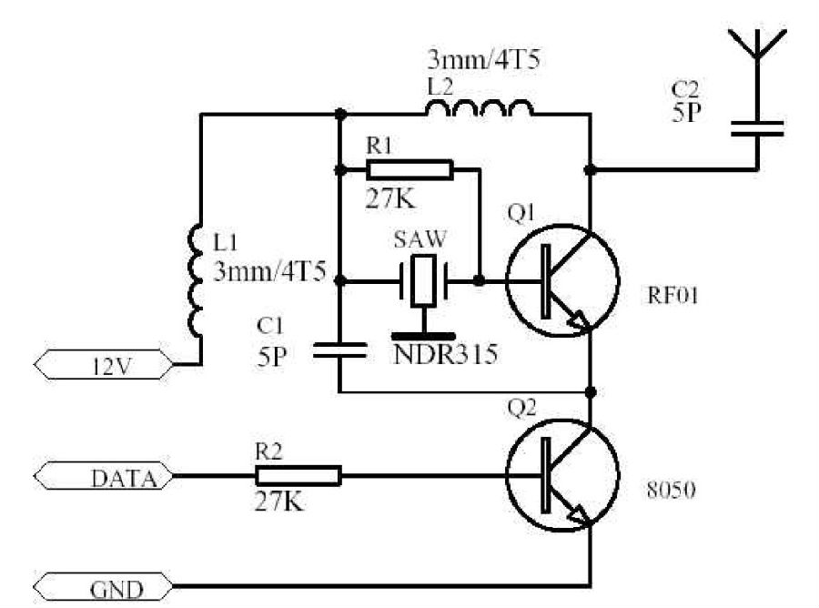
There are many types of wireless transmission circuits that use SAW resonators. Here is another circuit. This circuit was made by combining the actual samples of the module introduced in the article after referring to the article in the electronic newspaper 3 years ago. After mass production, some parameters have been improved, and now this product is really good. But now there are too many imitation products of Dongdong, and the quality is very different, but because it is relatively simple, I think it is necessary to show it to everyone. I also found many similar circuit diagrams on the Internet, but Some of them have pitfalls. I hope everyone should pay attention to learn to identify some bugs by themselves. For this module, I have not tested the jue pair power of its wireless transmission, but we drove the car over the distance on the road. It can reach a distance of 800 meters with the normal 315M super-regenerative receiver module. As long as the circuit reduces the value of the 8050 base resistance, the communication distance will increase to 1200 meters or even farther, but after a lot of experiments, it is proved that it is not very reliable. The reason is not very clear to me. There may be two reasons. One is that when R2 is small, the 8050 has a slight turn-on, which causes the launch to not be cut off quickly. Another is that R2 is very small, and the 8050 turn-on current is relatively large, which may be a disturbance to the power supply and fail to meet the vibration requirements. I once doubted whether my circuit is very matched, so I bought a lot of similar modules that claim to be 1500 meters, and found that they also have the same unreliability, generally showing that they occasionally fail to vibrate or the baud rate is less than 2K. Later, I increased the R2 resistor. When it was greater than 15K, the emission was always normal, and the distance was almost the same as that of 27K, so now I use this resistor. For L1L2 here, I use a 0.8mm drill bit that eliminates the enameled wire in 3mm. It is a semi-born product with 4 rounds of upper winding. During the production, there may still be some problems with the PCB wiring. I remind everyone that the wiring should be as simple as possible, and the wiring should be as short as possible. The components should be selected. The PCB board can be 1.5 mm thick.

Super regenerative receiving circuit. People always say that compared with super heterodyne, what’s wrong with it, bandwidth, anti-interference ability, bad radiation, as if it’s not good at anything. , Then I can tell you very clearly that most of the wireless receiving circuits used in anti-theft alarms on the market now use super-regenerative circuits. Almost all remote control toys use that stuff, so Well, its market is quite large, because its sensitivity is not comparable to that of superheterodyne, and debugging is simpler than superheterodyne. Many friends may have noticed that the high frequency and small inductors I use here seem to be PCBs. Why? The key is to be easy to do. Although I did a lot of experimental work when I did it, once it was confirmed, it was relatively stable. The following is a brief introduction to the circuit. The loop in the front is the PCB Inductor, and the adjustable capacitor at the back is used for tuning. The tuning method is to face the spectrum analyzer and adjust the local oscillator signal to the 315MHZ you want. If there is no spectrum analyzer If it is, then it is directed to the transmitter and slowly gathers it until it can be received. The weak data signal is input from the PCB inductance through the 10K resistor and 10UF capacitor to the base of T2. After preliminary amplification, it enters the LM358 to continue the shaping and amplification. The amplified digital signal is directly input to the signal input pin 14 of the PT2272 for decoding, and the decoded output pin is the 10-13 pin of the PT2272.
The radio remote control transmitter T630 is a miniature transmitter with a built-in wire and no signal. Its transmission frequency is 265MHz. When powered by a 12V power supply, the remote control distance is 100M, the working current is only 4mA, and its volume is 28X12X10mm.
The radio receiver T631, a built-in antenna, is a receiver and demodulator like a TV tuner. Its typical working voltage is 6V, standby working current is 1mA, receiving frequency is 265MHz, and its volume is only 31X23X10mm. They can be used to easily produce various radio remote control devices, which have the advantages of miniaturization, long transmission distance, low power consumption, and strong anti-interference ability. It can easily replace infrared, ultrasonic transmitter and receiver.
The circuit principle of the radio head T630 is shown in the figure. Circuit four transmitting tube V1 and peripheral components C1, C2, L1, L2, etc. constitute an ultra-high frequency transmitting circuit with a frequency of 265MHz, which is launched into the air through the loop antenna L2. Antenna L2 uses silver-plated wire or enameled wire with a diameter of 1.5mm, and the antenna size is 24mm (length) X 9mm (height). The triode V1 selects the high-frequency launch tube BE414 or 2SC3355.
The circuit principle of the radio remote control receiver T631 is shown in the figure. The receiving circuit is mainly composed of V1, IC, etc. V1 and C7, C9, L2 and other components form an ultra-high frequency receiving circuit. Fine-tune C9 to change its receiving frequency so that it is strictly aligned with the 265MHz transmitting frequency. When the antenna L2 receives the modulated wave, it is tuned by V1 to amplify the low frequency components, and then pre-amplified by V2 and sent to the IC LM358. After further amplification and shaping, it is output by the 7th pin of the LM358. The actual size of the printing is 31mmX23CC, and the antenna size is 27mm (length) X9mm (height). OUT is the signal output terminal, and the transistor V1 selects BE415 or 2SC3355.
The capacitor C9 can be a small adjustable capacitor. IC chooses LM358.
In order to reduce the volume in the transmitting and receiving circuit, all the resistors are 1/8W or 1/16W metal film resistors; the electrolytic capacitors are also ultra-small capacitors, and the other capacitors are all high-frequency ceramic capacitors. When soldering, the component pins should be cut as short as possible to make it close to the circuit board. The circuit board material should be a high-frequency circuit board.
The following are two-carrier transceivers that use surface acoustics. Compared with the circuits described above, they have a longer transmission distance, stronger anti-interference ability, and easier production and debugging.
Launch part
Receiving part

To add a bit of content, about the inductance in the circuit:
View more : IGBT modules | LCD displays | Electronic Components