TI designed the integrated visual development environment CCS (CodeComposerStudio) for the company’s DSP, and DSP/BIOS is an important part of CCS. It is essentially a real-time operating system kernel based on the TMS320 series DSP platform, and is also a core part of TI’s real-time software technology-eXpressDSP technology. DSP/BIOS mainly includes three aspects: multi-threaded kernel, real-time analysis tool, peripheral configuration library.
1 System function requirements
The main function of the power quality monitoring terminal is to monitor and analyze the power quality of the power grid (Three-Phase voltage and current) in real time. The main monitoring variables are: voltage and current effective value, active and reactive power, voltage frequency, three-phase unbalance, each harmonic voltage and current content rate, power factor, phase shift power factor, voltage fluctuation, long time, Flicker for a short time.
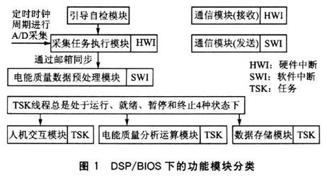
The system selects TI’s high-performance DSP chip TMS320F2812 as the processing core, and its 150MIPS processing speed is sufficient to meet the real-time requirements of the system. According to system requirements, the system is divided into the following functional modules: guided self-checking module, collection task execution module, power quality data preprocessing module, power quality analysis operation module, data storage module, communication module, and human-computer interaction module.
According to the traditional programming method, these functional modules will be organized together in a sequential structure, and the calls and switching between modules are completed by the code of each module, so that the modules of the application are in a coupled state. If you want to add a new function module or modify an existing function module, not only must the calling code of the related module be modified, but the new module will also obviously affect the time response characteristics of the original system, making the upgrade and maintenance quite troublesome .
The emergence of DSP/BIOS provides another mechanism for organizing the functional modules of application programs. It treats each functional module as a task thread. Through the configurable kernel service, each task thread multiplexes CPU resources according to the priority of the system scheduler. Each task thread passes synchronization, communication, and Data exchange, etc. are coordinated. This mechanism improves the maintainability of the application and provides a more convenient and advanced means of retesting. According to the above characteristics, this system adopts DSP/BIOS as the real-time kernel, and designs the whole system based on this.
Figure 1 shows the classification of the system’s functional modules under DSP/BIOS.

2 Software design based on DSP/BIOS
2.1 Execution thread planning
In the real-time operation of the system, some function functions are driven by external control signals or run in a predetermined period. Therefore, the driving mode and execution period of the function are very important to the real-time system. DSP/BIOS supports multi-threaded applications, and threads can be defined as different priorities.
High-priority threads can interrupt low-priority threads, and interactions between different threads, such as blocking, communication, and synchronization, are divided into the following 4 types (priority from high to low): Hardware Interrupt (HWI) , Software Interrupt (SWI), Task (TSK), Background Thread (IDL). According to the functional requirements of the power quality monitoring terminal system, the sub-function modules of the system are divided into the above 4 types of threads.
First, schedule the hardware interrupt thread (HWI). Under normal circumstances, the main program code of the system is placed in the software interrupt or task; however, the program code of the functional module that is closely related to the external device and requires high real-time performance must be placed in the hardware interrupt.
In accordance with the above requirements, the system sets the following sub-function modules as hardware interrupt threads: A/D acquisition task module and communication module (receive). A/D acquisition is an important foundation of this system, and it is closely connected with the underlying hardware of the system, so it is set as a hardware interrupt thread (HWI).
The main process is: the A/D chip collects real-time data of the power grid at a certain frequency, and then communicates with the McPSP port of the DSP. The DSP receives the data collected by the A/D chip and stores it in a specific area of the on-chip RAM to prepare for the operation of other threads. The communication module uses RS485 to communicate with the host computer, which is closely related to the underlying hardware of the system, and the SCI interface of the DSP itself has only a FIFO with a maximum of 16 words. If the received data is not processed in time, data will be lost.
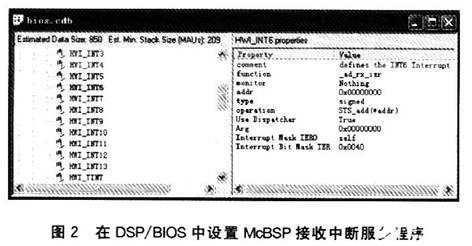
The following describes the parameter settings of the HWI module in DSP/BIOS. The receiving interrupt of the McBSP serial port is placed in the HWI_INT6 position of the HWI module, and the ISR function ad_rx_isr() of the receiving interrupt is filled in the function call item of the HWI_INT6 interrupt; at the same time, choose to use the HWI scheduling function of DSP/RI-OS, when responding to McBSP When the serial port receives an interrupt, the system will automatically call the ad_rx_isr() function. The McBSP serial port receiving interrupt setting is shown in Figure 2.
Similar to the setting of the McBSP serial port receiving interrupt, the SCIA receiving interrupt is set as the communication receiving interrupt, and its ISR function scia_rx_isr() is filled in the function call item of the HWI_INT9 interrupt. When responding to the receive interrupt, the system calls the scia_rx_isr() function for processing. The CLK thread is also one of the HWI hardware interrupt threads. It provides a time reference for the operation of the entire system, provides a method for users to call functions periodically, and provides a time reference for some code evaluation tools. The CLK module completely relies on the timer interrupt of the DSP. TMS320C2812 provides 2 timers for the DSP/BIOS.

Second, arrange the software interrupt thread (SWI). All software interrupts are initiated through the API call of the DSP/BIOS kernel. In order to facilitate control, the system sets a 16-bit mailbox (Mailbox) for each SWI object, which can be used to conditionally start the corresponding mailbox. Software interruption. The sub-function modules that are more important than ordinary tasks and occur frequently can be arranged in the software interrupt thread (SWI). Its sub-function modules include: power quality data preprocessing module, communication module (send).
The power quality data preprocessing module mainly completes the subsequent processing of the A/D conversion results. It is necessary to preprocess the A/D conversion result. Because the A/D chip selects a fixed frequency for acquisition, but the frequency fo of the power grid fluctuates, directly performing FFT operations on the acquired data will cause spectrum leakage. Therefore, the acquired data must be preprocessed. For example, a 1024-point FFT operation is performed on a total of 1024 data of 256 points for each of 4 cycles. Assuming that the average frequency of 4 cycles is f, the frequency resolution is f/4, and the FFT operation results are f/4, 2f/4, 3f/4, f, 5f/4… the intensity on the frequency. Therefore, when the power grid frequency fo changes, the power grid data frequency f for FFT calculation also changes accordingly, so that the power grid data frequency f before the FFT calculation is always consistent with the current power grid frequency fo.
The specific operation of the power quality data preprocessing module is to interpolate the data after A/D conversion, and the interpolation algorithm uses linear interpolation. After verification, under rated voltage, the error of FFT operation caused by linear interpolation algorithm is within 0. Within 1‰. In addition, another function of the module is to calculate the effective value of the voltage within a cycle. This is the necessary data for calculating voltage fluctuations and long-term and short-term flicker. The communication module (send) is responsible for sending data to the upper computer. Although its real-time requirements are not high, it is closely related to the bottom layer of the hardware, so it is set as a software interrupt thread.
When the serial port receiving interrupt occurs, call the scia_rx_isr() function to process the received data command, and send the corresponding power quality data according to the related command. DSP/BIOS provides a priority of 0 to 14 for the software interrupt object. According to the importance of the above thread, the priority of the collection data processing thread is set to 14, the host communication thread is set to 8, and other priorities are reserved for future software upgrades .
It should be noted that interrupt threads (including hardware interrupts and software interrupts) all run on the same stack. When a high-priority interrupt occurs and causes the system to switch tasks, the high-priority interrupt thread will interrupt the low-priority interrupt thread; before running the high-priority interrupt thread, the relevant register content of the low-priority interrupt thread will be saved, and the high-priority interrupt After the thread runs, the register will be restored to its original content and continue to complete the original low-priority thread.
Therefore, if too many hardware interrupts or software interrupt threads are set, the stack will overflow. For this reason, most task modules must be placed in task threads. Next, schedule the task thread (TSK). Like most real-time systems, task threads are the main component of the entire system. Functions in task threads can run independently or in parallel. The DSP/BIOS task management module arranges operation according to the priority of the task thread, and completes the conversion from one task to another task through the switching function.
Each task has 4 execution states: run, ready, blocked and terminated. The January mission is created, and it is always in one of four states. DSP/BIOS provides a priority of -l to 15 for each task object. Tasks will be executed in strict priority order, tasks with the same priority will be arranged in the order of execution according to the “first come, first served” principle. It should be noted that when a task thread is created, a dedicated stack belonging to the task needs to be created at the same time. The stack is used to store local variables or further function call nesting.
We set the power quality analysis calculation module, data storage module, and human-computer interaction module in the task thread (TSK). The power quality analysis calculation module can be divided into three parts: harmonic calculation task thread, voltage fluctuation calculation task thread, and flicker calculation task thread.
The harmonic calculation task thread is mainly responsible for performing FFT operations on the preprocessed power quality data. FFT operation mainly includes five parts: bit conversion operation, windowing operation, butterfly operation based on 2, split base operation, and square sum operation. The voltage fluctuation calculation task thread is responsible for recording the fluctuations of the grid voltage within 3 minutes. The previous power quality data preprocessing module has obtained the effective value of the voltage for each cycle.
In this way, it is only necessary to record the maximum and minimum values of the effective value of the voltage within 3 minutes, and the difference between the two is the voltage fluctuation. The flicker calculation task thread includes the calculation of short-time flicker and long-term flicker. Now the IEC flicker meter design method is generally adopted.
The input adaptive self-check signal passes through the quadratic demodulator, band-pass weighted filtering, squared first-order low-pass filtering, and online statistical evaluation to finally obtain the flicker value; but this method is sufficient Complex and time-consuming. By simplifying the algorithm, a simple and feasible calculation method is obtained: FFT calculation is performed on the effective voltage value of 256 consecutive cycles, and after a series of calculations such as weighting, the flicker value of 12.8s can be obtained, and the flicker value is within 10 minutes.
The value can get short-term flicker after correlation calculation, and 12 consecutive short-time flickers (within 2h) can get long-term flicker after calculation. After verification, this algorithm has an error within 1‰ compared with the IEC flicker meter algorithm.
The data storage module is also placed in the task thread, and its process is to store the power quality analysis results, voltage fluctuations and flicker values in FIash. The human-computer interaction module includes two parts: keyboard detection task and liquid crystal display task. The keyboard detection task thread can be completed by the periodic function PRD. PRD can determine the running time of the function according to the real-time clock. Here, set the keyboard detection task to run once in 100ms to detect keystrokes. According to the key condition, the liquid crystal display task displays the current latest power quality data.
Finally, there is the background thread (IDL). The background thread (IDL) has the lowest priority. Generally, the real-time analysis module (TRA) is placed in it to run, which can perform real-time interaction and diagnosis of the DSP application during the execution of the application. CCS has real-time analysis tools such as CPU load diagram, execution diagram, host channel control, information recording, statistical observation, real-time control board and kernel/object observation. This series of functional modules can be placed in the IDL thread, through these tools, the operation of the entire DSP system will be clear at a glance.
2.2 Communication and synchronization between threads
In this multi-threaded system, access to shared resources requires mutual coordination between threads to solve.
There are three communication methods in the DSP/BIOS environment, namely pipe-based (PIPE) communication, stream-based (SIO) channel-based communication, and host (HST) channel-based communication.
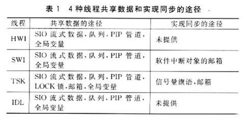
Table 1 shows the ways in which 4 threads share data and achieve synchronization.

3 System real-time analysis and debugging
The overhead of the DSP/BIOS kernel itself will have an impact on the real-time performance of the system program. For this reason, the DSP/BIOS kernel needs to be optimized. You can use the DSP/BIOS analysis tool provided in CCS to determine the DSP/BIOS overhead and the computing capacity of the entire application system. For example, the CPU load diagram in the real-time analysis tool provided by DSP/BIOS is one of the commonly used tools.
In the final integration stage, due to real-time interaction and other reasons, there will often be some errors or untimely responses. Generally speaking, because these phenomena are non-periodic and have a low frequency of occurrence, they are difficult to find and track. However, because the RTA module in the DSP/BIOS is embedded in its core, combined with the custom detection vector provided by the developer, it provides a unique visibility to the root cause of the error. This visualization function greatly helps isolate and correct errors, which is not available in general embedded development systems.
The execution performance of the application program in the entire system can be improved from the following four aspects: carefully select the thread type for different program functions; place the system stack in the on-chip memory; reduce the clock interrupt frequency; increase the size of the stream input and output buffer .
4 summary
As a set of tools provided by CCS, DSP/BIOS itself only occupies very little CPU resources, but it provides quite high performance and speeds up the development progress. Using DSP/BIOS as the real-time operating system of the power quality monitoring terminal, it is easy to control hardware resources when writing DSP programs, and to coordinate various software modules flexibly, which greatly accelerates the progress of software development and debugging. The final experiment proved that the whole system has good real-time performance and stable and reliable operation.