The true wireless stereo (TWS) market has exploded, growing at an estimated rate of more than 50% every year since the release of the Apple AirPods in 2016. Manufacturers of these popular wireless headsets are rapidly adding more features (noise canceling, sleep and health monitoring) to differentiate their products, but adding all of these features can be difficult from a design engineering perspective. In this article, I’ll review these challenges.


Fig. 1: Example of a true wireless stereo application with earbuds and charging case (Image: Texas Instruments Inc.)
Challenge No. 1: Minimizing power loss with efficient charging
A primary challenge for wireless headsets is to achieve a longer total play time after fully charging the earbuds in the battery case. In this case, a longer total play time translates to the number of cycles that the case can charge the earbuds throughout its lifetime. The goal is to achieve high-efficiency charging while minimizing power loss from the charging case to the earbuds.
The charging case outputs a voltage, derived from its battery, that serves as the input to charge the earbuds. The typical scheme is a boost converter that outputs a fixed 5 V, which is a simple solution but does not optimize charging efficiency. Because earbuds have very small batteries, designers often employ linear chargers. The charging efficiency when using a fixed 5-V input is low – roughly (VIN-VBAT)/VIN – and creates a large dropout voltage to the battery. Plugging in the average lithium-ion (Li-ion) battery voltage of 3.6 V (halfway discharged), the efficiency with a 5-V input comes to just a 72% charge.
Conversely, using an adjustable output boost or a buck-boost converter in the charging case creates a voltage just barely above the typical voltage range of the earbuds. This requires communication from the charging case to the earbuds, which enables the charging-case output voltage to dynamically adjust to the earbuds’ battery as voltage increases. This will minimize the dropout, increase the charging efficiency and reduce the heat significantly. Fig. 2 shows an example of such a system.

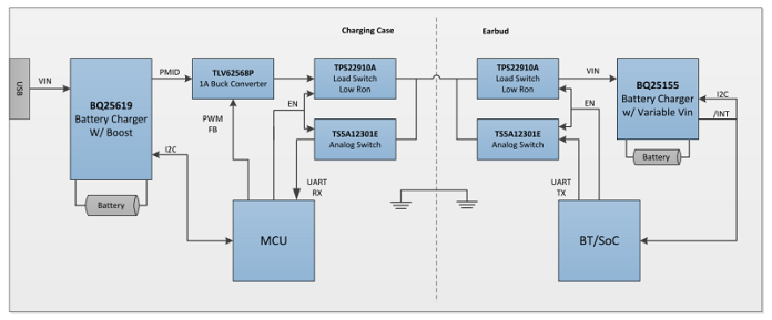
Fig. 2: High-efficiency charging system for a wireless headset using a two-pin interface (Source: TI application report SLUAA04)
Challenge No. 2: Shrinking overall solution size without removing features
The second challenge is a universal one for small battery designs – how to design for both small size and greater functionality. The simple solution here is to choose devices with more integrated components. For example:
- A high-performance linear charger that integrates additional power rails to supply the main system blocks is a good option for wireless headsets.
- For power-hungry and low-voltage blocks such as processors and wireless communication modules, switching rails are the best choice for efficiency.
- For sensor blocks that don’t need much power but do require low noise, consider low-dropout regulators.
- If the wireless headset integrates analog-front-end sensors to measure blood oxygen and heart rate, you may also need a boost converter.
The integration of extra power rails into the charger enables a smaller form factor. There is always a trade-off, however, between integrating more to get smaller vs. using more discrete integrated circuits (ICs) to gain flexibility.
Challenge No. 3: Extending standby time
Standby time is important because consumers expect their headsets to be ready to play music even after idling for a long time outside the charging case. Consider employing higher-energy-density Li-ion cells in the earbuds, which usually come with higher voltages like 4.35 V and 4.4 V, and thus pack more energy. A fuller charge will increase standby time as well. A battery charger that features a small termination current with high accuracy will help extend standby time as well. If the termination current specification has a wide variation, you may end up getting the termination current on the higher side, which results in early termination and an undercharged battery.
Fig. 3 shows a case where a 41-mAh battery terminates at 1 mA vs. 4 mA. If the nominal 1-mA termination current has a wide variation and actually terminates at 4 mA, a 2-mAh battery capacity will remain untapped. A lower termination current and higher accuracy increases the effective battery capacity.


Fig. 3: A 41-mAh battery with a 1-mA nominal termination current actually terminates at 4 mA. (Image: Texas Instruments Inc.)
Low quiescent current (IQ) in different working modes is also important to help extend standby times. A charger IC with a power path and nearly zero ship-mode current will prevent the battery from draining before the product gets to the consumer, supporting immediate use. Power path entails the placement of a metal-oxide Semiconductor field-effect Transistor (mosfet) between the battery and system to manage the system and battery paths separately.
When the earbuds are playing music or idle, the system current consumption needs to be as small as possible. Look for a charger that has a low IQ and also minimizes the system’s IQ. For example, battery chargers often need a negative temperature coefficient (NTC) Resistor network to measure the battery temperature. The BQ21061 and BQ25155 chargers from Texas Instruments, for example, integrate a current source to bias the resistor network, which can be off when not taking measurements.
Some solutions on the market cannot turn off the NTC current when operating in battery mode. They will either have excessive leakage (the leakage can get to more than 200 µA when the NTC network has 20 kΩ from the bias voltage to ground) or require an extra input/output and switch to shut it off.
Challenge No. 4: Designing for safety
Battery-pack manufacturers usually have guidelines for charging their batteries at different temperatures, and it’s imperative for the battery to remain in these safe operating zones while in use. Some require a standard profile where charging stops outside of cold and hot temperature boundaries. Others may require specific profiles from the Japan Electronic Information Technology Association, for example. To be compliant with these temperature profiles, look for batteries with the necessary built-in profile or some I2C programmability. The BQ21061 and BQ25155 have registers to set the temperature window and actions to take in specific temperature ranges.
Battery undervoltage lockout (UVLO) is another safety feature, keeping the battery from overdischarging and thus being stressed. UVLO cuts off the discharge path once the battery voltage goes below a certain threshold. For example, for a Li-ion battery that has 4.2-V full charge voltage, a common cutoff threshold is 2.8 V to 3 V.
Challenge No. 5: Ensuring system reliability
Low system reliability can cause some microprocessors to get stuck when the consumer plugs in the adapter. Although this is rare, it requires a system power reset so that the microprocessor can reboot and return to normal. Some battery chargers integrate a hardware reset watchdog timer that performs a hardware reset or power cycling if no I2C transaction is detected for some time after the consumer plugs in the adapter. Upon system reset, the power path disconnects and reconnects the battery and system.
Similar to a hardware reset watchdog timer, a traditional software watchdog timer also helps increase system reliability by resetting the charger registers to default values after a period of no transactions in I2C. This reset prevents false battery charging when the microprocessor is in a fault condition.
Challenge No. 6: Monitoring optimal operating zones
The sixth challenge is to monitor the system parameters, which a built-in high-precision analog-to-digital converter (ADC) can do efficiently. Measuring the battery voltage is a good parameter because it expresses the battery state of charge conveniently, although in an approximate way. As a rule of thumb, you’ll need a dedicated battery-gauge IC if the wireless headset requires a state of charge higher than ±5%.
A high-precision built-in ADC also enables you to monitor the temperature of the battery and board during charging and discharging and take action. Other parameters that a charger can monitor include input voltage/current, charge voltage/current and system voltage. Built-in comparators are also convenient to help monitor specific parameters and send an interrupt to the host. The host doesn’t have to read parameters of interest constantly if the parameters are within normal limits and don’t trigger the comparators. The BQ25155 is a good example of a device that can monitor system parameters, as it has an ADC and comparators.
Challenge No. 7: Facilitating easy wireless connectivity

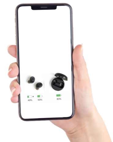
Fig. 4: TWS state-of-charge report on a smartphone (Image: Texas Instruments Inc.)
Some wireless headsets have a feature to display the state of charge of both the earbuds and charging case on a smartphone when the earbuds are in the charging case and the lid is open. To support this feature, the earbuds have to report the state of charge instantly when inserted into the case, even if the batteries are deeply discharged. The main chip has to be awake to report the state of charge, so in this instance an external source has to power the earbuds. Chargers that have a power path enable the system to have a higher voltage from VBUS while charging the battery at a lower voltage.
Several features for wireless headsets chargers – such as ship mode, system power reset, battery UVLO, accurate termination current and instant state-of-charge reporting – are not possible without a power-path feature, which entails the placement of a MOSFET between the battery and system to manage the system and battery paths separately. Fig. 5 illustrates chargers with and without the power path.
It is common to see both switching and linear chargers in a charging case design, depending on the battery size and charging rate. Switching chargers have higher efficiency and generate less heat, which is important for large currents 700 mA and higher. Switching chargers usually come with an integrated boost or on-the-go function, which can boost up the battery voltage to provide an input voltage for the earbuds to charge. Linear chargers are also good choices for battery cases at lower current levels, as they offer low cost and low IQ.
Rechargeable hearing aids have similar design challenges. They are often smaller than earbuds so as to appear invisible, and thus need more power integration in a smaller area. They also require low-noise power rails, including one with a switched capacitor topology, for superior audio clarity.

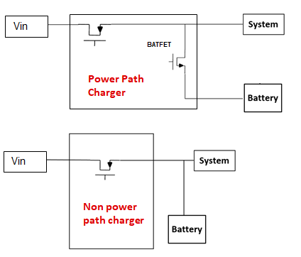
Fig. 5: Battery chargers with and without a power path (Texas Instruments Inc.)
The battery-charger IC will remain an important element in TWS product designs as manufacturers continue seeking performance, feature, and size enhancements. Be sure to consider high-performance chargers for the challenges discussed in this article.
Additional resources
- Read these application reports:
- “High-Efficiency Charging for TWS Using a 2-Pin Interface.”
- “BQ21061 Two-Layer Small Form Factor Design for Cost Optimized PCBs.”
- Download the BQ25155 setup tool to generate a microcontroller code for programmed values.
- Search for the right TI battery-charger IC for your next design.
about Texas Instruments