Differential-mode and common-mode currents can cause your product to produce radiated and conducted emissions. These three techniques can help you measure them.
If you’ve dealt with EMC issues for any length of time, you’ve probably run into the term “common mode currents,” which often lead to radiated emissions. Common mode (CM) and differential mode (DM) currents from the power input of power supplies can cause conducted emissions from cables. Worldwide limits on conducted electromagnetic interference (EMI) can cause product to fail compliance tests.
Several mechanisms create common-mode currents (ICM). Differential mode currents (IDM) result from the input voltages driving switching power-conversion circuitry. CM currents usually result from power-device switching noise that gets capacitively-coupled to reference planes or chassis structure. The rectification and power switching cause high harmonic switching currents. We use input filtering to minimize this switching noise (EMI) from coupling to the mains or DC input port.
Figure 1 shows how the different sections of the line filter affect both the DM and CM currents. For example, the “X” capacitor plus the DM inductance of the choke can reduce DM EMI. In the same way, the “Y” capacitors plus the CM inductance of the choke can reduce CM EMI. The ability to separately measure the DM and CM EMI contributions lets us specify the appropriate filter component values to minimize this coupled EMI.


The usual method for evaluating conducted emissions (CE) is through a line impedance-impedance stabilization network (LISN). Unfortunately, this only plots the combination of DM and CM EMI on either the Line or Neutral sides of the AC mains input. To properly design the input filter, we really need to measure the DM and CM EMI separately.
There are three methods I’ve used to help separate the DM and CM noise components: RF current probes, a device from Tekbox called “LISN Mate,” and a new analyzer by EMZER, called EMScope.
RF current probe method
This is probably the simplest method. RF current probes, when connected to a spectrum analyzer, can measure the very small RF harmonic currents that produce conducted EMI. By clamping the current probe around both the line and neutral wires, we measure the total CM EMI (Figure 2).


By reversing one of these wires (does not matter which), we measure twice the DM EMI, which is 6 dB higher (Figure 3).


Figure 4 shows the combined plots of DM and CM EMI. We can see the DM voltage is higher than the CM at the lowest frequencies in the case of this AC power supply.


LISN Mate method
Evaluating power supplies for conducted emissions requires a LISN. Tekbox Digital Solutions released a device called LISN Mate (Figure 5). LISN Mate includes circuitry that splits DM harmonic signals from CM, which is valuable for evaluating filter circuits. Tekbox specifies it from 30 kHz to 110 MHz but characterizes it up to 150 MHz.


To split DM and CM using the LISN Mate, requires two LISNs connected as in Figure 6.

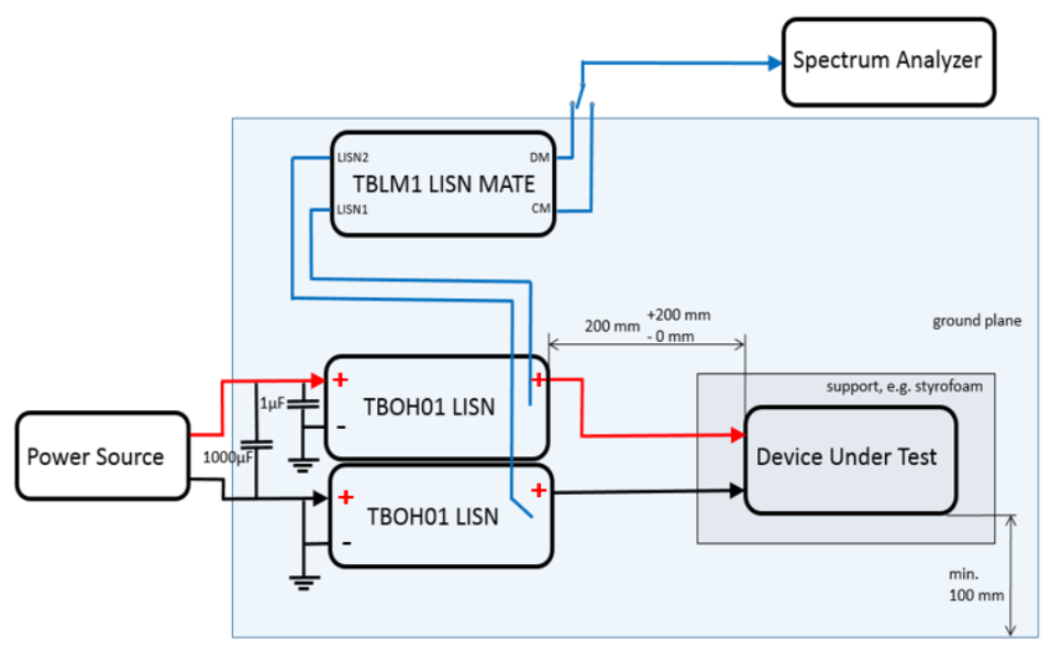
Figure 7 shows the DM and CM EMI from a TI TPS54525 DC-DC converter demo board. Two separate Tekbox TBOH01 DC LISNs were used. The DM plot is higher than the CM plot in this case, so I’d start off with the DM filter, such as an “X” capacitor across the DC input. Likely, we’d also need a CM choke or at least a series inductor in the +DC line.

Being able to see the difference in DM versus CM EMI, we can specify just the right filter components.
EMScope method
The EMScope (Figure 8)is an all-in-one instrument that contains two 50 µH LISNs and a spectrum analyzer that covers 9 kHz to 30 MHz (an option extends to 110 MHz) and can display conducted emissions (Line-Gnd, Neutral-Gnd), DM or CM EMI, or a combination of all four in a single display. It also has peak, quasi-peak, and average detectors and can display any combination or all three together. Because EMScope is a real-time FFT-based analyzer, the sweeps are fast, with updates for all displayed traces about every second.


Figure 9 shows the resulting DM and CM plots from an older Utilitech LED 60 W (equiv.) light bulb as compared to the CISPR 15 EMC standard for luminaires. It fails badly.


I enjoy the ease and versatility of the EMScope and the fact it can be used with any web browser.
Power-line filter kit
I’ll close this article by mentioning one of my favorite kits from Würth Elektronik: the “Design Your Filter Kit,” number 744998 (Figure 10). This kit can help you design EMI filters for DC or AC applications. The included instruction manual helps select the right component depending on the DM or CM plots measured using the above three methods.


Summary
While RF current probes are somewhat pricey, they are also the easiest to use to separate DM and CM EMI. The Tekbox LISN Mate would be useful if you’re setting up a test bench specifically for measuring power supply emissions. Once set up, the measurements are relatively quick.
I like the versatility of the EMScope and at less than $10k, would be a valuable addition to your test bench. It will not only display DM and CM EMI, but conventional line and neutral conducted emissions, with either peak, quasi-peak or average detection, all displayed at once or in combinations Thus, it works well for pre-compliance or even compliance testing, as well as assisting with filter design.