Many designers are including audio codecs in their microcontroller-based embedded system designs in an effort to add high-fidelity audio. In doing so, they have to figure out how to tune the audio codec for their application. Without tuning, the application may be left sounding flat or of poor quality, even with a good codec and speaker. The problem is that every speaker has its own frequency response and so the codec should be tuned to the speaker characteristics while keeping in mind the kind of audio that will be played and the required response.
The solution to tuning the audio playback system is not to use hardware filtering but instead, leverage the audio codec’s own digital filtering blocks. Every codec has this block to allow a developer to filter the output using high-pass, low-pass and bandpass filters. This allows the speaker response to be carefully tuned and even adjusted, as necessary.
This article will discuss the internal digital audio blocks that are included in codecs, using a codec from AKM Semiconductor as an example. It will also discuss several tips and tricks on how to tune the codec that will help developers accelerate their audio playback development while improving a system’s sound quality.
Understanding speaker frequency response characteristics
The article “How to Select and Use an Audio Codec and Microcontroller for Embedded Audio Feedback Files” discussed the fundamentals of selecting and adding a codec to a system. The next step is to use that codec to get the best possible audio output.
There are several different factors that contribute to how the audio coming out of a system will sound. These factors include:
- The speaker’s enclosure
- How the speaker is mounted
- The audio frequencies that are being played
- The frequency response of the speaker
After careful consideration of these factors, a developer will soon realize that tuning an audio system is useful only when it’s in its final production state. Sure, the system can be tuned with a printed circuit board (pc board) and the speaker outside a housing, but one shouldn’t expect those same tuning parameters to apply when the speaker is mounted and within its enclosure.
If the mechanical team has properly designed the system enclosure and mount, the main characteristic that the developer needs to watch closely is the speaker frequency response. Every speaker has different characteristics and response curves. Even speakers with the same part number will often have slight variations in frequency response, but the manufacturer usually provides a typical frequency response curve. For example, Figure 1 shows the frequency response curve for a CUI Devices GC0401K 8 Ohm (Ω), 1 watt speaker. The GC0401K is rated for frequencies between 390 Hertz (Hz) and 20 kilohertz (kHz).
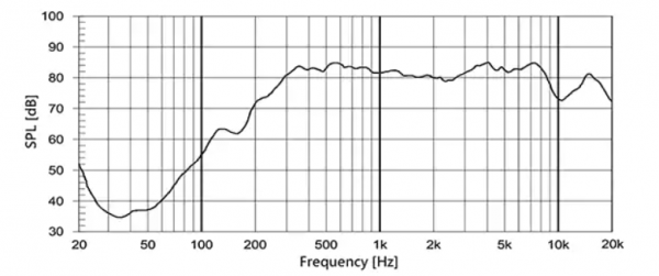

Figure 1: The CUI Devices’ GC0401K 8 Ω, 1 watt speaker is rated for frequencies between 390 Hz and 20 kHz. (Image source: CUI Devices)
Speakers are typically rated for the region of their response curve where the response is relatively flat. A close look at Figure 1 shows that the frequency response for the GC0401K starts to flatten at ~350 Hz and stays relatively flat at least through 9 kHz. The high-end frequencies have some drop-off but are still stable up to 20 kHz.
A different speaker frequency response can be seen in CUI Devices’ GF0668 (Figure 2). This speaker is a little bit larger and can output 3 watts. The frequency response rating is between 240 Hz and 20 kHz. This speaker can hit slightly lower frequencies than the GC0401K, but note again that within the specified range the curve is relatively flat with some troughs and peaks throughout.
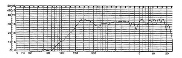

Figure 2: The frequency response for CUI Devices’ GF0668 8 Ω, 3 watt speaker shows why it’s rated for the range of 240 Hz to 30 kHz. (Image source: CUI Devices)
One last speaker response worth looking at is Soberton Inc.’s SP-2804Y (Figure 3). The SP-2804Y is a 500 milliwatt (mW) speaker with a frequency response range of 600 Hz to 8 kHz. The laws of physics ensure that the smaller the speaker, the tougher the time it has responding to lower frequencies. This means that if developers don’t filter out lower frequencies and instead try to drive the speaker at those frequencies, the result can be some gnarly-sounding audio or defects in tones that would otherwise sound crystal clear.
Notice there is also a significant dip in the frequency response around 10 kHz. Therefore, the speaker is only rated to 8 kHz even though it probably could be used up to 20 kHz for some applications.
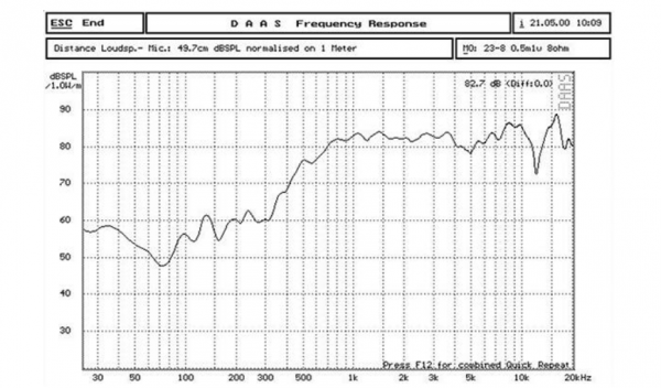

Figure 3: The frequency response for Soberton Inc.’s SP-2804Y 8 Ω, 0.5 watt speaker shows it’s suited to frequencies from 600 Hz to 8 kHz. It has a dip after 10 kHz but it’s still usable out to 20 kHz for some applications. (Image source: CUI Devices)
Looking at each speaker’s frequency response, it’s clear that some kind of filtering and tuning needs to take place as there are some frequencies at which a speaker should not be driven. For example, trying to drive a 4 Hz bass tone on these speakers could cause long-lasting vibrations upon which higher frequencies are injected, resulting in lots of sound distortion.
Dissecting an audio digital filter block
One method that has been used in the past to tune out unwanted frequencies is to build hardware filters leading up to the speaker. For example, a high-pass filter at 500 Hz can prevent frequencies below 500 Hz from ever making it to the speaker. At the other end, a low-pass filter can be used to remove any audio tones above 15 kHz. Personal experience has shown that sometimes if a woman’s voice is being used with a small speaker that is efficient at higher frequencies, the speaker can exhibit a high-pitched twang. Carefully selecting the frequencies can remove these distortions and create cleaner sounding audio.
While external hardware filters can do the job, they add cost and take up additional space. For these reasons, it’s more practical and efficient to tune the audio using the digital filter block built into an audio codec.
For example, the block diagram for the AKM Semiconductor AK4637 24-bit audio codec has the digital filter block highlighted (Figure 4).
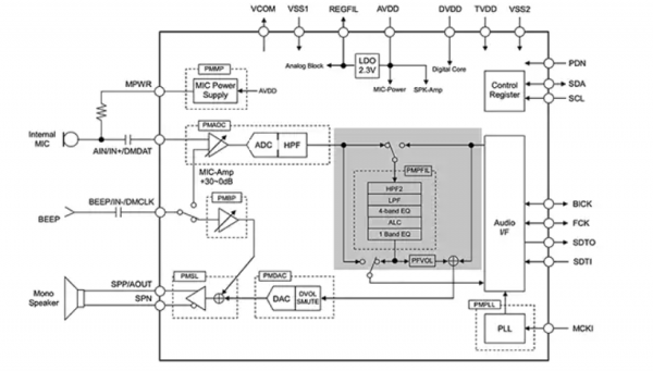

Figure 4: The AK4637 is an audio codec with a mono speaker output that has audio playback and recording capabilities. It also contains an internal audio block that can be used to filter incoming and outgoing audio to improve audio fidelity. (Image source: AKM Semiconductor)
The digital filter block in this case contains several different filtering capabilities which include:
- A high-pass filter (HPF2)
- A low-pass filter (LPF)
- A four-band equalizer (4-Band EQ)
- Automatic leveling control (ALC)
- A one-band equalizer (1 Band EQ)
These features don’t all need to be enabled. Developers can select which features they need and enable and disable the block or route microphone or playback audio through them. The real question at this juncture is how to calculate and program the audio codec?
How to calculate and program digital filter parameters
In most audio applications, a high-pass filter is used to remove lower frequencies and a low-pass filter is used to exclude higher frequencies. An equalizer may be used to smooth out the frequency response curve or to emphasize certain tones. How exactly these settings should be selected is beyond the scope of this article. It will instead look at how to calculate and program the values that are associated with these parameters using the AKM AK4637 as an example.
First, it is always a good idea to review the datasheet. Pages 7 and 8 in this case show the all-important register map for the codec. A first look might be intimidating given that the part has 63 registers. However, many of these registers control the digital audio block. For example, registers 0x22 through 0x3F control the equalizer. Registers 0x19 through 0x1C control the high-pass filter, while 0x1D through 0x20 control the low-pass filter.
Developers usually can’t just specify a frequency to input into the codec. Instead, there is a filter equation that is used to calculate filter coefficients, which are then programmed into the codec registers to create the filter at the desired frequency. For example, to use the digital filter block to create a high-pass filter at 600 Hz, use Equation 1:
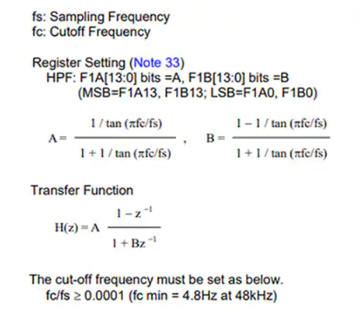

Figure 5: Shown are the equations needed to calculate the coefficients for a high-pass filter for the AK4637 digital filter block. (Image source: AKM Semiconductor)
A developer would identify the desired cutoff frequency, fc, which in this case is 600 Hz. The audio sampling frequency, fs, is typically 48 kHz, but can vary based on the application. These values would then be placed in the equations for calculating coefficients A and B. These values are then written to the codec registers over I2C during start-up. The same process would be used for the low-pass filters and other digital block features, although the transfer functions are often different, requiring their own set of equations to be used (refer to the datasheet).
Tips and tricks for tuning an audio codec
The digital filter blocks included in an audio codec are often quite flexible and powerful. Even a low-cost audio codec provides developers with the tools necessary to generate high-fidelity audio. At the end of the day though, the audio codec is just one piece of the puzzle. To successfully tune an audio codec, there are several “tips and tricks” developers should keep in mind such as:
- Ensure that the speaker is mounted in an appropriate enclosure for the application. An improperly designed speaker box can easily ruin an otherwise perfect playback system.
- Don’t tune the codec audio filter blocks until the system is fully assembled in its production intent configuration. Tuning parameters might otherwise change.
- Select the frequency range based on the audio that will played. For example, the frequency settings for music from a guitar, piano or someone speaking will all be different.
- Use the digital balance block to compensate for the frequency response of the speaker. Some frequencies will naturally sound louder and clearer and may need to be attenuated, while others may need to be amplified.
- Use test tones to evaluate the frequency response of the system. A simple Internet search will provide mp3 files for a wide range of audio tones that can be used to understand the frequency response of the audio playback system and how the digital filter block is working.
- Store the filter block configuration settings in flash or EEPROM so that they can be set during manufacture to account for system-to-system variations (if that is of concern).
Developers that follow these “tips and tricks” will find that they save quite a bit of time and grief when attempting to tune their audio playback system, and ensure it gets to market with the intended audio characteristics.
Conclusion
Adding an audio codec to an embedded systems does not guarantee that it will sound good to the end user. Every audio playback system needs to be carefully tuned. It’s possible to use external filters to achieve this tuning, but audio codecs come with digital filtering and balance capabilities built in. As shown, these can be used to feed the speaker only the frequencies for which it is best suited. With careful analysis and application of filter settings, developers can create the clean-sounding audio that end users have come to expect from their devices.