5G brought passive intermodulation problems into the spotlight. Now it’s up to engineers and technicians to identify and mitigate signal degradation to minimize dropped calls and other issues.
By Danny Sleiman, EXFO
A loose connection; a metal roof; power lines. Even a rusty bolt. It’s estimated that mobile operators will spend $1.1 trillion on capital expenditure between 2020 and 2025, much of it allocated to creating, improving, and maintaining its advanced networks — a little corrosion can result in decreased data rates or dropped calls.
Passive intermodulation (PIM) interference is not a new problem for the mobile industry, but it is growing. PIM has become a pressing problem due to the rapid deployment of new technologies, the use of frequency bands located close to each other that are particularly susceptible to this issue, and the increasing number of subscribers. These factors have combined to create a challenging environment where PIM can cause significant disruption and degradation in the performance of wireless networks.
What is PIM?
PIM is the generation of interfering signals caused by nonlinearities in a wireless network’s passive components. The interaction of mechanical components — such as loose cables, dirty or corroded connections, or metal-on-metal connections such as fasteners — can produce PIM. When two signals pass through these components, the signals can interfere with each other, creating harmonics that fall directly into the uplink band. Networks can transmit and receive 4G/5G signals without ever seeing an issue. In busy networks with multiple frequency bands transmitted, however, the chances of causing RF interference increase.
Mobile networks aim to make the best use of the frequencies they license, meaning this is a problem — especially at the crowded lower-band 450 MHz to 1 GHz and mid-spectrum 1 GHz to 6 GHz bands used by many operators for 5G services. Higher frequencies and less crowded networks may be less prone to PIM interference.
The third harmonic is often the strongest in PIM because it is the result of the second-order nonlinear mixing of two input signals, which generates an intermodulation product at three times the frequency of one of the input signals (see Figure 1 and Table 1). The result is an increase in the noise level affecting desired signals, leading to dropped calls and decreased capacity. To compensate, the power levels of the cellular site will increase so that the signal can be separated from the noise. This spike in power is a big flag to the network that a problem exists, but also creates its own issues.
Table 1. The math behind IMD and PIM shows
where distortion products occur.
| Order (IMx) | Frequencies | Tone 1 | Tone 2 | |
| 1st order | f1 | f2 | 100 MHz | 101 MHz |
| 2nd order | f1 + f2 | f1 – f2 | 201 MHz | 1 MHz |
| 3rd order | 2f1 – f2 | 2f2 – f1 | 99 MHz | 102 MHz |
| 2f1 + f2 | 2f2 + f1 | 301 MHz | 302 MHz | |
| 4th order | 2f2 + 2f1 | 2f2 – 2f1 | 402 MHz | 2 MHz |
| 5th order | 3f1 – 2f2 | 3f2 – 3f1 | 98 MHz | 103 MHz |
| 3f1 + 2f2 | 3f2 + 2f1 | 502 MHz | 503 MHz | |
| 7th order | 4f1 + 3f2 | 4f2 – 3f1 | 97 MHz | 104 MHz |
| 4f1 + 3f2 | 4f2 + 3f1 | 703 MHz | 704 MHz | |
| 9th order | 5f1 – 4f2 | 5f2 – 4f1 | 96 MHz | 105 MHz |
| 5f1 + 4f2 | 5f2 – 4f1 | 904 MHz | 905 MHz | |
PIM becomes more apparent when cell sites experience high levels of activity with numerous user devices connected to the network. As the site attempts to overcome the noise and interference within the network, it may need to increase power levels, which can further exacerbate PIM. An example of compensating for noise in a crowded environment is speaking louder so that the listener can hear your message. In situations where the noise level is high, we naturally adjust our vocal volume to ensure that our message is effectively communicated. Similarly, cell sites trying to overcome noise interference increase their power levels to compensate, which can affect nearby cell sites.
Detecting the sources of PIM interference
Knowing that an interference problem exists in a network can be straightforward. The previously mentioned increased power use is a big clue, and many networks have fault-detection software that can point to where interference exists. Unfortunately, identifying the sites where PIM interference exists and knowing what is causing the interference at these sites are very different challenges. The origins of PIM interference can be extremely difficult to pinpoint.
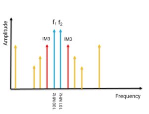

Figure 1. Intermodulation (IMD) creates distortion that degrades signal quality, causing PIM. The third harmonic is usually the worst offender.
First, there are two types of PIM. Internal PIM is caused by the internal RF elements in the infrastructure such as loose connectors, damaged cables and connectors, and faulty elements in the antennas. These issues typically occur between the transmitter and the antenna, and the most common culprit is a damaged or faulty coaxial cable. External PIM is caused by objects located near cell sites. Examples include metallic objects (usually rusty) close to the antenna, metal roofs, or even digital billboards. Interference from either of these domains is difficult to identify.
Dealing with internal PIM can often require a specialist crew climbing a cell tower or accessing a rooftop to look for what might be causing the problem. Those situations entail expense and risk, especially carrying a bulky PIM analyzer. Even then, there’s no guarantee of identifying the problem the first time, so multiple truck rolls may be necessary to find and detect every potential source of PIM. While a corroded coaxial connector is the most likely suspect, this is not guaranteed; the entire process of finding and resolving an internal PIM issue can take weeks to complete. This is due in part to the required analysis, which can be a mostly manual effort rather than using automated technology.
External PIM can be even more difficult to locate. Technicians need to hunt down and pinpoint the source (or sources) causing the interference, and the solution may not be easily apparent. A spectrum analyzer can help pinpoint the source, and the process of interference hunting is highly manual and typically requires RF expertise. In extreme circumstances, the only solution may be to move the site completely.
Making this bad situation even worse, it’s not immediately obvious when the problem is external or when it is internal. Analysis can mean disconnecting the site from the network for assessment, which is far from ideal for an operator striving to keep customers connected. Technicians have a short window to try and resolve issues so that customers don’t suffer too much disruption.
Easier PIM hunting
The nature of PIM interference makes it a particular headache for operators, given that it’s common, hard to pin down, and resolving it can be expensive. Plus, an extended hunt for PIM interference can cause more problems than it solves. As engineers search for the problem and change connections and hardware, they can end up introducing elements that make the PIM interference worse, not better. Fortunately, there are ways to mitigate these issues.
RF analysis over Common Public Radio Interface (CPRI)
It may seem counterintuitive in a mobile network that diagnosing PIM issues can involve both fiber and over-the-air RF testing. In fact, by using RF spectrum analysis over the fiber or CPRI protocol, technicians can isolate whether the issue is internal or external PIM. To perform the RF spectrum analysis over the fiber (or CPRI), technicians attach an optical splitter near the baseband unit at the bottom of an antenna tower to diagnose the PIM issue. Performing this analysis from the ground avoids the time and effort of a technician scaling a tower to address interference.
A major benefit is that RF spectrum analysis over the fiber is a passive test application, so the baseband unit and remote radio head will continue to process calls normally, allowing technicians to analyze the uplink spectrum during normal site operation — and during busy periods when PIM is most active.
This type of analysis requires specialist equipment as it must be attuned to different network components — and network equipment from different or multiple vendors means that the encrypted signals along fiber are not simple to analyze. Processes are available to auto-detect vendors’ proprietary signals, which reduces the configuration by applying intelligence and automation.


Figure 2. PIM blankets shield antennas and other passive components, which helps isolate PIM sources (Image: ConcealFab).
PIM blankets
One way to detect if a particular fastener or bolt is causing external PIM interference is to fix or replace it. This isn’t always ideal — if the problem remains then an engineer or technician has spent valuable time and resources repairing something that hasn’t solved the issue. One way around this is quite simple: throw a PIM blanket over the offending item (Figure 2). These suppress the RF signal, meaning it no longer interferes with the site. This way the process of elimination is faster and repairs can be carried out on items that are actually worth fixing.
Spectrum analyzers
For situations where the internal or external PIM is not readily diagnosed at a particular site, over-the-air spectrum analyzers with interference hunting connected to a PIM probe or a directional antenna can enable anyone to hunt down the causes of ongoing PIM interference (Figure 3). Many solutions to PIM problems use multiple tools and are too complex to use without advanced expertise, but investing in intelligent equipment means field technicians can detect problems more quickly.
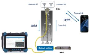

Figure 3. This test setup uses a spectrum analyzer connected to a cell site’s CPRI optical interface to hunt PIM issues.
Given that PIM interference causes slower data rates and dropped calls, any customer making regular use of a site is likely to already be suffering from issues. Extended downtime while the problem is located will only make this worse, so ensuring quick resolution is important.
PIM will never go away
Wherever we have wireless technology, we have PIM because it’s impossible to eliminate entirely. Thus, it’s a consideration that operators need to take seriously. Networks are only going to become more crowded as new technologies increase data throughput and more cell sites are built to cope with demand.
Operators need to approach this with a proactive as well as a reactive approach. The reactive approach will always be necessary, of course. Many sites were built to support older technologies and were upgraded for LTE and now 5G. When these upgrades were in place, problems with PIM became apparent. As PIM is often a result of infrastructure degradation, then dealing with PIM is simply part of ongoing maintenance.
But there are steps that operators can take to prevent PIM issues. As metal-on-metal connections are often a big problem, sites can use plastic fasteners and connections so that these issues don’t arise — stainless steel might be durable, but that doesn’t matter if it’s causing interference. Operators can take other steps to prevent the corrosion of materials. Potential PIM sources can be identified and mitigated before they become an issue.
All network planning, building, and maintenance needs to be carried out with PIM mitigation in mind, not just taking today’s technology into consideration but tomorrow’s as well. The shift to 5G revealed some big PIM issues, so what about 6G? Or even further? What about when new bands are made available? Completely future-proofing against PIM interference is impossible, but the negative impact of PIM can be lessened with the right approach.