“Before threading the residual current transformer, the phase wires, N wires and PE wires in the power grid should be distinguished. The phase wire and the N wire must pass through the residual current transformer together, and the PE wire cannot pass through the transformer. In the system, if the N line does not pass through the transformer together with the phase line, once the Three-Phase load is unbalanced, current will flow through the N line, and the detector detects the current signal and malfunctions.
“
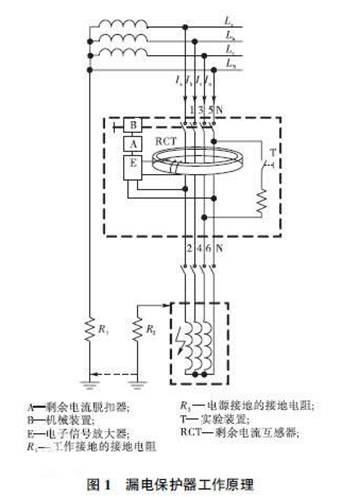
Working principle of residual current transformer
The structure principle of the leakage protector is shown in Figure 1.

Installation and wiring method of residual current transformer and matters needing attention
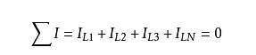
The grid wire passes through the magnetic core of the RCT, and the RCT detects the phasor sum of the current of the protected circuit.Under normal circumstances, the currents of each phase are balanced, and the phasor sum of one side current I through RCT is equal to zero, which can be known from Kirchhoff’s current law

Installation and wiring method of residual current transformer and matters needing attention
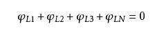
In this way, the sum of the magnetic flux Φ generated by the working current of each phase wire in the toroidal core of the current transformer is also zero, that is


Installation and wiring method of residual current transformer and matters needing attention
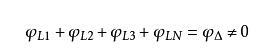
When someone gets an electric shock or other ground leakage fault, due to the existence of leakage current, the phasor sum of each phase load current (including the neutral current) passing through one side of the current transformer is no longer zero, that is, at this time


thereby

The working principle of RCT is shown in Figure 2.
The secondary coil of the RCT generates an induced potential E2 under the action of the alternating magnetic flux ΦΔ, thereby generating an induced current IΔ proportional to the leakage current in the secondary circuit. The greater the leakage current, the greater the induced potential E2 of the secondary winding. The relationship between the two is shown in Figure 3. Among them, curve 1 is the no-load characteristic when the secondary winding of the transformer is open. It can be seen that the induced potential E2 of the secondary side is very small at the beginning, and only after the leakage current I1 of one side increases to a certain value, E2 will be obvious. After that, with the increase of I1, E2 keeps getting bigger and changes approximately linearly; when I1 reaches a certain value, the change of E2 tends to be slow, even showing a downward trend, and the linearity becomes worse. This is because the magnetic core enters Caused by the saturation zone. Therefore, the appropriate secondary side load impedance should be selected to ensure that the magnetic core works in the linear section to avoid magnetic saturation of the magnetic core.Curve 2 is the load characteristic under the working state with a trip unit. Due to the demagnetization of the secondary side load current, the magnetic core becomes less likely to saturate, and under the same leakage current condition, E2 is relatively small
1. Thread the residual current transformer
Before threading the residual current transformer, the phase wires, N wires and PE wires in the power grid should be distinguished. The phase wire and the N wire must pass through the residual current transformer together, and the PE wire cannot pass through the transformer. In the system, if the N line does not pass through the transformer together with the phase line, once the Three-Phase load is unbalanced, current will flow through the N line, and the detector detects the current signal and malfunctions. The N wires between different circuits should not be connected at many points or repeatedly grounded, otherwise it will cause malfunctions, and an alarm will occur when the leakage current value is too large during the system trial operation. A large part of this is caused by such conditions. If the PE wire passes through the transformer together with the N wire and the phase wire, it will also cause the monitoring detector to fail or malfunction.
Not all residual current monitoring needs to pass the phase wire into the transformer. The total residual current monitoring method of the TN-S system can be excluded. It can only pass through the residual current transformer through a cable. The advantage of this method is that a small residual current transformer can be used to improve the measurement jing degree; if the transformer fails later, it is convenient to maintain. The specific wiring diagram is shown in the figure.
2. Installation position of residual current transformer
The residual current transformer should be installed in a place that is convenient for inspection and repair, as far away as possible from the strong magnetic field. There is no direction problem in the installation of the transformer. The transformer can be directly hung on the cable or fixed in the distribution box.
The installation of the residual current transformer and the upper or lower end of the switch circuit breaker will not affect the monitoring of the protected circuit. However, in order to facilitate future maintenance, it is better to install it at the lower port of the switch. It is not necessary to power off the upper switch when the power is off for maintenance, and only the switch of this level can be opened for maintenance.
3. Precautions for the wiring of residual current transformers
1. Be sure to distinguish the phase wires, N wires and PE wires in the power grid before wiring, otherwise problems will occur, resulting in inaccurate measurement data and false alarms.
2. The phase line and the N line must pass through the residual current transformer together, and the PE line cannot pass through the transformer, which will also affect the deviation of the circuit parameters, so be careful.
3. If the N line does not pass through the transformer together with the phase line, once the three-phase load is unbalanced, current will flow through the N line, and the detector will detect the current signal, resulting in misoperation.
4. If the PE line passes through the transformer together with the N line and the phase line, it will also cause an error alarm of the monitoring detector, which will seriously affect the normal operation of its work.
5. The N wires between different circuits should not be connected at many points or repeatedly grounded, otherwise it will cause malfunctions, and an alarm will occur if the leakage current is too large, most of which are caused by this reason.
The correct wiring method can enable the normal operation of the fire monitoring detector and effectively prevent the occurrence of electrical fires.
Working principle of residual current transformer
The structure principle of the leakage protector is shown in Figure 1.

Installation and wiring method of residual current transformer and matters needing attention
The grid wire passes through the magnetic core of the RCT, and the RCT detects the phasor sum of the current of the protected circuit.Under normal circumstances, the currents of each phase are balanced, and the phasor sum of one side current I through RCT is equal to zero, which can be known from Kirchhoff’s current law

Installation and wiring method of residual current transformer and matters needing attention
In this way, the sum of the magnetic flux Φ generated by the working current of each phase wire in the toroidal core of the current transformer is also zero, that is
Installation and wiring method of residual current transformer and matters needing attention
When someone gets an electric shock or other ground leakage fault, due to the existence of leakage current, the phasor sum of each phase load current (including the neutral current) passing through one side of the current transformer is no longer zero, that is, at this time
thereby

The working principle of RCT is shown in Figure 2.
The secondary coil of the RCT generates an induced potential E2 under the action of the alternating magnetic flux ΦΔ, thereby generating an induced current IΔ proportional to the leakage current in the secondary circuit. The greater the leakage current, the greater the induced potential E2 of the secondary winding. The relationship between the two is shown in Figure 3. Among them, curve 1 is the no-load characteristic when the secondary winding of the transformer is open. It can be seen that the induced potential E2 of the secondary side is very small at the beginning, and only after the leakage current I1 of one side increases to a certain value, E2 will be obvious. After that, with the increase of I1, E2 keeps getting bigger and changes approximately linearly; when I1 reaches a certain value, the change of E2 tends to be slow, even showing a downward trend, and the linearity becomes worse. This is because the magnetic core enters Caused by the saturation zone. Therefore, the appropriate secondary side load impedance should be selected to ensure that the magnetic core works in the linear section to avoid magnetic saturation of the magnetic core.Curve 2 is the load characteristic under the working state with a trip unit. Due to the demagnetization of the secondary side load current, the magnetic core becomes less likely to saturate, and under the same leakage current condition, E2 is relatively small
1. Thread the residual current transformer
Before threading the residual current transformer, the phase wires, N wires and PE wires in the power grid should be distinguished. The phase wire and the N wire must pass through the residual current transformer together, and the PE wire cannot pass through the transformer. In the system, if the N line does not pass through the transformer together with the phase line, once the three-phase load is unbalanced, current will flow through the N line, and the detector detects the current signal and malfunctions. The N wires between different circuits should not be connected at many points or repeatedly grounded, otherwise it will cause malfunctions, and an alarm will occur when the leakage current value is too large during the system trial operation. A large part of this is caused by such conditions. If the PE wire passes through the transformer together with the N wire and the phase wire, it will also cause the monitoring detector to fail or malfunction.
Not all residual current monitoring needs to pass the phase wire into the transformer. The total residual current monitoring method of the TN-S system can be excluded. It can only pass through the residual current transformer through a cable. The advantage of this method is that a small residual current transformer can be used to improve the measurement jing degree; if the transformer fails later, it is convenient to maintain. The specific wiring diagram is shown in the figure.
2. Installation position of residual current transformer
The residual current transformer should be installed in a place that is convenient for inspection and repair, as far away as possible from the strong magnetic field. There is no direction problem in the installation of the transformer. The transformer can be directly hung on the cable or fixed in the distribution box.
The installation of the residual current transformer and the upper or lower end of the switch circuit breaker will not affect the monitoring of the protected circuit. However, in order to facilitate future maintenance, it is better to install it at the lower port of the switch. It is not necessary to power off the upper switch when the power is off for maintenance, and only the switch of this level can be opened for maintenance.
3. Precautions for the wiring of residual current transformers
1. Be sure to distinguish the phase wires, N wires and PE wires in the power grid before wiring, otherwise problems will occur, resulting in inaccurate measurement data and false alarms.
2. The phase line and the N line must pass through the residual current transformer together, and the PE line cannot pass through the transformer, which will also affect the deviation of the circuit parameters, so be careful.
3. If the N line does not pass through the transformer together with the phase line, once the three-phase load is unbalanced, current will flow through the N line, and the detector will detect the current signal, resulting in misoperation.
4. If the PE line passes through the transformer together with the N line and the phase line, it will also cause an error alarm of the monitoring detector, which will seriously affect the normal operation of its work.
5. The N wires between different circuits should not be connected at many points or repeatedly grounded, otherwise it will cause malfunctions, and an alarm will occur if the leakage current is too large, most of which are caused by this reason.
The correct wiring method can enable the normal operation of the fire monitoring detector and effectively prevent the occurrence of electrical fires.
The Links: G156HTN021 CLAA170EA09