“Before 5G, most wireless device testing was done using the wire method. This includes testing modem chipsets, radio frequency (RF) parameter testing, and complete device function and performance verification. Over-the-air (OTA) testing methods are mainly used for antenna performance testing and device multiple input multiple output (MIMO) performance measurement. 5G millimeter wave (mmWave) devices represent a disruptive change in the wireless industry, because OTA is the only feasible test method for all radio test cases.
“
Before 5G, most wireless device testing was done using the wire method. This includes testing modem chipsets, radio frequency (RF) parameter testing, and complete device function and performance verification. Over-the-air (OTA) testing methods are mainly used for antenna performance testing and device multiple input multiple output (MIMO) performance measurement. 5G millimeter wave (mmWave) devices represent a disruptive change in the wireless industry, because OTA is the only feasible test method for all radio test cases.
At mmWave frequencies, higher path loss and shorter wavelengths require a controllable directional antenna (gain)-usually a phased array antenna. In addition to traditional LTE and Frequency range 1 (FR1) monopole antennas, many 5G devices also require multiple sets of mmWave antennas. Since the mmWave antenna must be directly connected to the RF front-end (RFFE) amplifier, it is impossible to access and test the equipment in a lower frequency manner, and radiation testing methods are required.
Traditional conducted RF testing methods use high-performance coaxial cables between the measurement solution and the device under test (DUT). OTA replaces this cable with an air link through which the DUT communicates directly with the antenna that is part of the test solution. In order to ensure a good RF environment (that is, test transmission lines and eliminate external interference), OTA connections are best managed inside the dark room.
Therefore, typical OTA measurement solutions include RF measurement equipment and darkrooms. The darkroom has several basic components:
The housing itself has proper RF isolation and internal shielding, which can minimize the internal reflection of the signal
The measurement antenna or “probe” antenna provides the main RF measurement link for the DUT
The locator can change the direction or position of the DUT
Software for controlling positioners and measuring equipment.
When choosing the correct settings for the desired measurement, the engineer needs to consider several factors. But first, a quick review of the relevant rules of thumb for electromagnetic fields.
Let’s start with wave transmission
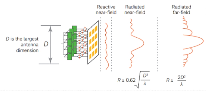

Figure 1. The difference between reactive near field (reactive NF), radiated near field (radiated NF) and radiated far field (radiated FF)
As the distance of the antenna increases, the behavior and characteristics of the electromagnetic field will change. The simplified model above shows three areas of interest: reactive near field (reactive NF), radiated near field (radiated NF), and radiated far field (radiated FF). When performing OTA measurements, the characteristics of each area must be considered, and the distance between the DUT and the probe antenna must be considered. For example, measuring in NF requires near-field-to-far-field conversion (NF-FF) software, which requires phase recovery or control of the input phase to the DUT. In this figure, R is the radial distance from the antenna, D is the diameter of the smallest sphere that can surround the aperture of the radiating antenna, and λ is the wavelength (Figure 1).
The reaction NF is the area closest to the DUT antenna. Not only does the non-propagating evanescent field dominate in this area, but the detection antenna in this area will also react with the DUT antenna and effectively become a part of the DUT radiating device. The type of measurement performed imposes significant restrictions.
The radiated NF is the area where the detection antenna no longer reacts with the DUT antenna, but the field behavior and phase front are less predictable and perform well. Measurements in this area also require access to phase recovery in the transmit and receive paths of the compensation algorithm.
Radiation FF is an area where the phase front can be estimated to be approximately flat. This area is very suitable for measuring phase and amplitude, but the disadvantage is that the path loss is large, and the distance between the DUT and the probe antenna is large (sometimes even bulky).
So, what are the key considerations for engineers to define OTA measurement settings?
Range length: the distance between the probe and the DUT
The range length must be optimized to obtain stable and accurate measurement results. As mentioned above, if you need to measure in FF, the range length is best kept at a distance greater than R = 2D2/λ.
Therefore, the size of the chamber is directly affected by the wavelength (frequency) in question and the size of the device antenna. For example, the far field range of a 5cm antenna at 28GHz is about 50cm. For a 10 cm module of the same frequency, it needs to be increased to 190 cm, and for a 15 cm device, it needs to be increased to more than 4 m (Figure 2).
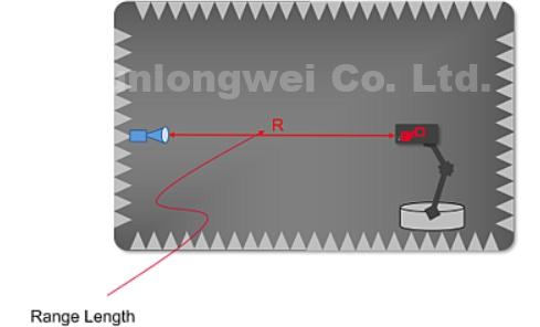

Figure 2. Range length
DUT: Device characteristics in mmWave OTA test setup
The DUT ranges from the radiating element to the entire device. In a mobile phone, the DUT will create a “D” (Device), which includes the mechanical size of the antenna and the coupling with the radiating element. The Third Generation Partnership Project (3GPP) has defined three DUT antenna configurations, including (Figure 3):
Configuration 1: DUT has at most one antenna panel, and the maximum aperture is equal to or less than 5 cm at any time.
Configuration 2: DUT has multiple antenna panels, the maximum aperture of each antenna panel is equal to or less than 5 cm, but in the absence of coherence, this means that they can be treated as independent panels
Configuration 3: DUT has multiple antenna panels, and there is phase/amplitude coherence between these panels, which means that they cannot be regarded as independent panels and “D” must enclose them all.
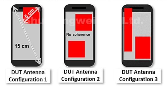

Figure 3, DUT antenna different configurations
Black box testing
Black box testing is a device conformance testing concept specified by 3GPP. Engineers must consider the location and number of antennas as unknown, DUT is tested as a “black box”, and must assume that the aperture of the antenna (D) is the same as the size of the entire DUT Therefore, the device configuration has an impact on the range length required for FF measurement (Figure 4).
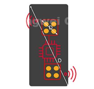

Figure 4. Black box test
Quiet zone
The quiet zone refers to the area where RF propagation can be predicted and performed well. This is very important for accuracy and repeatability, especially for the testing of RF parameters or when low amplitude and phase changes are required. The quiet area needs to be large enough to contain the key items being tested-whether it’s the entire device or the antenna. The size of the device under test or the antenna determines the requirements for the size of the quiet zone. Of course, the greater the quiet zone required, the larger the chamber required (Figure 5).
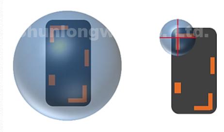

Figure 5, a schematic diagram of the quiet zone
CATR: Another method of DFF OTA testing
The compact antenna test range (CATR) is an indirect far field (IFF) OTA test method. CATR uses shaped reflectors to perform the physical near-field to far-field transformation. This results in a shorter range length and a larger quiet zone, so according to a given DUT size, aperture size and frequency reduce the size of the chamber. The beam reflected from the parabolic mirror becomes a collimated beam. This transition from a spherical wavefront to a plane wavefront results in a large quiet zone with very small amplitude and phase ripples. The resulting shorter distance also means that the path loss between the DUT and the probe is smaller, so that a better measurement dynamic range and a better signal-to-noise ratio (SNR) can be obtained (Figure 6).
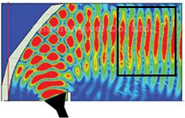

Figure 6 Compact antenna test range (CATR)
5G means that mmWave OTA testing is becoming a more mainstream requirement. These types of measurement challenges are undoubtedly new areas for most commercial wireless industries. It is very important to cooperate with mmWave and OTA test experts, who have also participated in the 3GPP specifications to gain early knowledge and demand impact. For decades, Keysight has been providing commercial mmWave test functions and has established the world’s leading mmWave OTA test solution series.
The Links: LM150X08-TL06 LM215WF3-S2L4