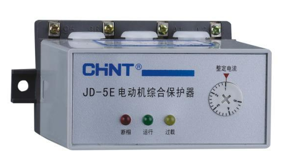
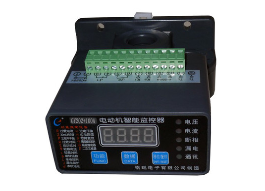
At present, the motor protector has been developed from the mechanical type to the Electronic type and intelligent type, with high sensitivity, high reliability, multiple functions and convenient debugging. It can directly display the current, voltage, temperature and other parameters of the motor. After the protection is activated, the type of fault is clear at a glance, which greatly facilitates the judgment of the fault, and is conducive to the fault handling at the production site and shortens the recovery time. In addition, the motor eccentricity detection technology based on the air gap magnetic field of the motor makes it possible to monitor the motor wear status online. The curve shows the change trend of the value reflecting the motor eccentricity, and the change of the value over a period of two years can be recorded to detect bearing faults early. Achieve early detection and early treatment to avoid the occurrence of sweeping accidents.
contents
- 1. Principle of motor protector
- 2. Wiring diagram of motor protector
- 3. What is the role of the motor protector
1. Principle of motor protector
The motor protector is composed of a Three-Phase current transformer, detection, amplification, delay, adjustment Circuit and executive Relay. When the detection circuit detects that the current induced by the current transformer is out of phase or greater than the set value, it is amplified by the amplifier to make the relay operate.
The relay contacts are connected in series in the power supply circuit of the contactor coil. After the relay operates, the contactor is powered off to protect the motor. The delay circuit is used to avoid the starting current of the motor, and its duration is adjustable. The adjustment circuit is used to accurately set the action current according to the working current of the protected motor.

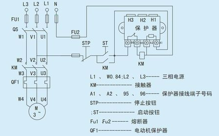
2. Wiring diagram of motor protector
The wiring method of the motor protector is as follows:
1. Phase loss protection L1~L3. Three current transformers are sampled, and the threshold potential is obtained on the Resistor R4 through the AND gate composed of three transistors U9~U11. When the phase is lacking, as long as one of the transistors is cut off and a low potential is formed on R4, the red light-emitting diode will be on, indicating a lack of phase. At the same time, the capacitor C6 is quickly charged, and the 555 time base on the left of NE556 forms the comparison unit.
2. After the motor is started in normal operation, the sampling potential of the current transformer will not be higher than the internal comparison potential of the time base during normal operation. The multi-resonant circuit also becomes a comparison circuit. The OUT2 output terminal of NE556 becomes high potential, and the green LED is always on, indicating that it is operating normally.
3. Overload protection When overloaded, the sampling potential on R4 is higher than the internal comparison potential of the time base. With the increase of overload or the increase of time, the sampling potential on R4 will increase relatively. Therefore, the frequency of the multi-resonant circuit will also increase. Corresponding to the OUT2 output terminal of NE556, the high and low alternately change (the only shortcoming is: the current sampling of this motor integrated protector has only one phase). Once the potential becomes low, the monostable circuit capacitor C6 starts to charge and is charged according to the changing frequency.

3. What is the role of the motor protector
The function of the motor protector is to provide a comprehensive protection and control for the motor. When the motor has overcurrent, undercurrent, open phase, locked rotor, short circuit, overvoltage, undervoltage, leakage, three-phase imbalance, overheating, grounding, bearing wear, When the stator and rotor are eccentric, the winding aging will give an alarm or protection control.