Audio power
One thing you find in the broad field of electrical engineering is that different industries and even companies may use different languages to describe the same topic. For a successful design, power and audio engineers must understand each other.
The first two terms that need to be defined are peak power and continuous power. The peak power is the ZD instantaneous audio power. It will determine how much power is designed for the physical output power supply. Continuous power is the audio power averaged over a period of time. In the context of power supply design, continuous power is the specified output power that the system can provide without exceeding the component temperature or average current rating. Figure 1 provides examples of peak and continuous audio levels. They are related to the crest factor, which is a measure of the ratio of the peak value of a waveform to the root mean square (RMS) value.
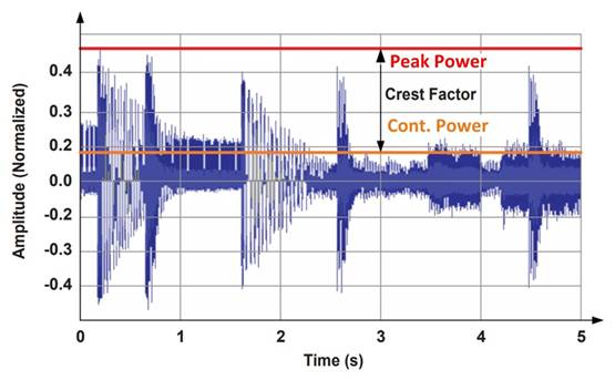
Figure 1 This graph shows continuous and peak power audio levels.

It can also be expressed in decibels using the following equation:

Formula for calculating audio level
RMS is a misnomer for audio power, because this value is not technically a calculated RMS value of the power waveform. You can write another article on how to specify the complexity of audio amplifiers. Understanding the industry standards for rated amplifier power levels does not necessarily clarify what the power requirements are in terms of peak and continuous power.
For example, consider the LLC series resonant converter (LLC-SRC) design for a 400W audio amplifier. Without prior knowledge of audio systems, you can design an excellent 400 W power supply. But when the amplifier needs to be powered up, the power supply fails, or the audio quality is poor. The LLC converter gain curve is usually designed according to the ZD load and works near the series resonant frequency under ZX line conditions. This method usually produces a perfect 400-W LLC-SRC, but in an actual audio system, the peak power will actually be greater than the 400-W rating of the amplifier. Before starting the power supply design, at least the continuous power and peak power should be specified.
For the 400 W amplifier example, the appropriate power level for consumer products to play compressed music can be 200 W continuous power and 800 W peak power for 15 milliseconds. This represents a crest factor of 12 dB, which is a typical value for processing music. Unprocessed audio is about 18-20 dB, and movie audio may be greater than 20 dB. In the end, the ratio of peak power to continuous power depends on the specific application, so it is very important to clearly define these early in the design process. The duration requirements for different load levels also help to optimize the design. Keep in mind that the efficiency of the audio amplifier needs to be considered, because there will be losses in the amplifier, which results in a higher load on the power supply.
LLC-SRC design
After the specifications are determined, you can proceed with the power supply design. Depending on the power quality standards of the region and application, you may need a power factor correction (PFC) power supply for this power level design. The PFC front end will provide a stable 400VDC bus for use as the input of LLC-SRC.
Like most resonant converters, the DY step of LLC-SRC design is to select resonant tank components. This will set the resonant frequency and shape the gain curve. In this step, ensure that the output voltage can reach the peak power level. If the resonant tank cannot achieve the required gain, the output voltage will drop at the audio peak, thereby reducing the audio quality or turning off the amplifier. For output Capacitors, the peak power duration requirements are usually too long to maintain the output voltage, so the power supply needs to be able to actually provide the entire peak load.
Add some extra space to the peak gain. The physical limitations of the transformer structure do not always reach the exact number of turns or inductance. For audio designs that require high peak power, it is advantageous to use discrete resonant inductors to ensure a more JQ resonance and magnetizing inductance.
At peak power, it is important to select components rated to handle peak currents. When designing magnetic components, make sure that they do not saturate. Under continuous power, it is important to select components and packages based on continuous thermal performance. Designers can reduce the size of some packages and use PCBs for thermal management instead of heat sinks.
Like any LLC-SRC, the shaping of the gain curve is an iterative process. Trying to reach a specific operating frequency, resonant current and voltage, and balancing the design between peak and continuous power levels is a challenge. In the calculation, you need to adjust the magnetizing inductance, resonance inductance, turns ratio and resonance capacitance. 100 kHz is a common resonant frequency target for silicon-based designs. For audio applications, it makes sense that the target frequency of the continuous power operating point is 100 kHz. Figure 2 shows the gain curve for the above example.