Acousto-optic control refers to an Electronic control method that uses sound and light changes to control Circuits to achieve specific functions. The acousto-optic control time-delay power-saving Circuit includes sound control, light-controlled sensing elements, amplifiers and a monostable delay circuit composed of 555 and a step-down rectifier circuit.
contents
- 1. What is the sound and light control delay switch
-
2. Working principle of sound and light control delay switch
-
3. Wiring diagram of sound and light control delay switch
1. What is the sound and light control delay switch
Acousto-optic control refers to an electronic control method that uses sound and light changes to control circuits to achieve specific functions. The acousto-optic control time-delay energy-saving lamp circuit includes sound control, light control sensing elements, amplifiers and a monostable circuit composed of 555 and a step-down rectifier circuit.
It is an energy-saving electronic switch that has no internal contact point and uses sound effects to stimulate the pickup to perform sound-to-electric conversion under specific ambient light to control the turn-on of electrical appliances. After a delay, it can automatically disconnect the power supply. It is widely used in corridors, building corridors, washrooms, toilets, factories, courtyards and other places. It is an ideal modern green lighting switch and prolongs the service life of bulbs.


2. Working principle of sound and light control delay switch
Voice control is to collect sound through pole microphone and generate pulse signal. The light control circuit is controlled by a photoresistor. The photoresistor has a large difference in resistance between light and no light, which can generate high and low levels and control the circuit through logic devices. The delay circuit is composed of a charging and discharging circuit composed of a Resistor and a capacitor, and is realized by the charging and discharging of the capacitor. The most commonly used delay circuit is 555, which relies on external Capacitors and resistors to control the time, which is easy to calculate. The disadvantage is that the delay time cannot be very accurate.
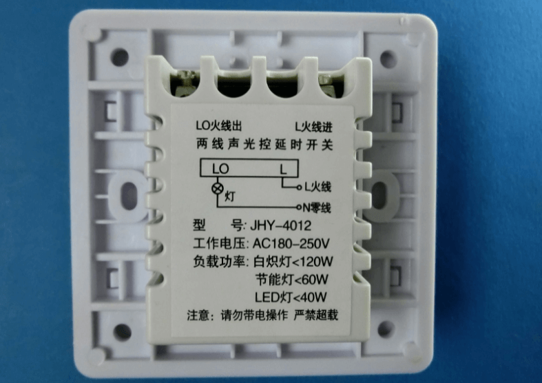

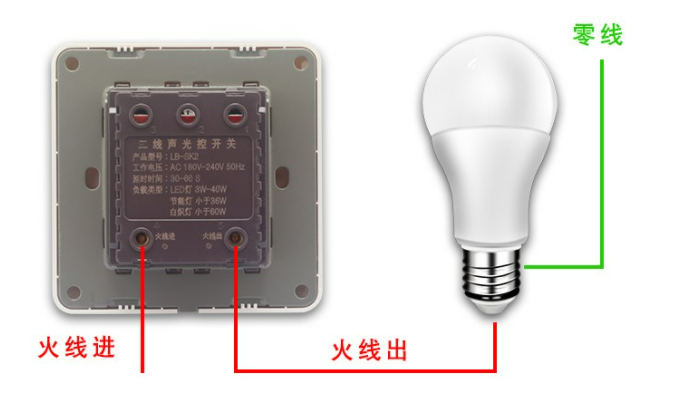
3. Wiring diagram of sound and light control delay switch
In order to control the cost, the manufacturer uses a low-power SCR in the voice-activated switch, so that the controlled power does not exceed 40W, and the fluorescent lamp has a large starting current when it is started, so it cannot be used. If you want to control high-power electrical appliances, you need to connect a 220V Relay to solve the problem.
Why must the wiring of the voice-activated lamp holder be connected to the zero live wire? And can’t use energy-saving lamps and can only install incandescent lamps?
The connection method of the sound and light control lamp holder is irrelevant to the zero fire line! The reason why you can only use incandescent lamps and not energy-saving lamps is that the sound and light control switch circuit rectifies the mains bridge, and then uses a one-way thyristor to control it. In fact, it turns the AC mains into a half wave. Electricity, that is, when the thyristor is turned off, there is still a small current flowing. This current is not enough to light up the incandescent lamp. It is different if the energy-saving lamp is installed. In the energy-saving lamp circuit, bridge rectification is followed by electrolytic filtering. When this current flows into the energy-saving lamp After the bridge rectification, the electric energy is stored in the filter electrolysis. When the electrolysis current is large enough, the energy-saving lamp will light up, and it will be extinguished when the electrolysis discharge is completed. Therefore, energy-saving lamps with sound and light control switches will have a flashing phenomenon.