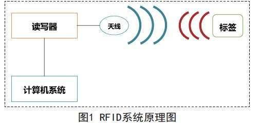
“One of the technologies of IoT is RFID. Do you know the working principle of RFID component RFID reader and Electronic tag? In fact, the two components of RFID communicate through antennas, using inductive coupling. Next, let’s take a look at the working principle of the RF front-end of RFID inductive coupling!
“
One of the technologies of IoT is RFID. Do you know the working principle of RFID component RFID reader and Electronic tag? In fact, the two components of RFID communicate through antennas, using inductive coupling. Next, let’s take a look at the working principle of the RF front-end of RFID inductive coupling!

Summary points
(1) Understand the concept of coil inductance and mutual inductance.
(2) Understand the concept of series-parallel resonance Circuits.
(3) The radio frequency front end of the RFID reader adopts a series resonance Circuit.
(4) The radio frequency front end of the RFID electronic tag adopts a parallel resonant circuit.
(5) RFID readers and electronic tags transmit information through inductive coupling.
(6) Understand the concepts of load modulation and power matching.
Concept analysis
(1) Resonant circuit, the resonant circuit can selectively pass signals of a part of the frequency while attenuating signals outside the passband.
(2) Resonant circuit parameters. We often use parameters such as resonant frequency, quality factor, input impedance and bandwidth to describe the resonant circuit.
(3) Resonant frequency, that is, the capacitive reactance of the resonant circuit is equal to the inductive reactance after the external signal is input into the resonant circuit at a specific frequency. This specific frequency is the resonant frequency, which is also called the operating frequency.
(4) The quality factor is defined as the ratio of the average energy storage to the power loss of the resonant circuit. It is often expressed by the ratio of characteristic impedance to loop resistance. Therefore, the Q factor is a dimensionless parameter.
Series resonance and parallel resonance
“Series resonant circuit” series resonant circuit
“Parallel Resonance Circuit” Parallel Resonance Circuit
Small summary:
(1) The calculation formula of the resonant frequency of the series resonant circuit and the parallel resonant circuit is the same.
(2) The smaller the resistance R of series resonance and parallel resonance, that is, the smaller the circuit loss, the higher the quality factor, that is, the better the signal selectivity, and the narrower the bandwidth BW.
(3) The load quality factor is usually actually used. Due to the energy loss of the external load, the load quality factor will decrease. This is the calculation of the external quality factor.
Inductive coupling
“Inductive coupling” inductive coupling
Small summary:
(1) Inductive coupling is adopted between the RFID reader and the electronic tag. The reader provides energy to the electronic tag through the inductive coupling and transmits information and communication at the same time. Inductive coupling is in accordance with Faraday’s law of electromagnetic induction.
(2) Adjust the output voltage of the electronic label. The electronic label obtains the AC voltage, and then outputs the DC temperature voltage after passing through the full-wave rectifier circuit, filter circuit and voltage stabilizing circuit.
(3) The electronic tag transmits data to the reader through load modulation, that is, the load modulation adjusts the electrical parameters of the electronic tag’s oscillation circuit according to the data flow, and encodes and modulates the data to transmit data information.
(4) Load modulation has two methods: resistive load modulation and capacitive load modulation. The external load must match the power.
The structure of RFID radio frequency front end
Whether it is for RFID readers or RFID electronic tags, the structure of the radio frequency front end needs to meet the requirements:
(1) The current and induced voltage on the antennas of RFID readers and electronic tags are increased, causing the reader coils to generate large magnetic flux, and the induced output voltage of the electronic tag coils is large.
(2) Power matching, the reader can output energy to the electronic tag to a large extent, and the electronic tag is coupled with the energy of the reader to a large extent.
(3) Sufficient bandwidth BW is required to enable the signal of the reader or electronic tag to be transmitted without distortion.
(4) For low-frequency or high-frequency RFID, inductive coupling is used, while for radio frequency (radio frequency (300K-300G) is the higher frequency band of high frequency; microwave frequency band (300M-300G) is the higher frequency band of radio frequency). Using electromagnetic backscattering method.
The Links: CLAA150XP07FQ EPM7512AEQC208-10N