We built the circuit shown in Figure 1 and described it. This circuit can be used in the automotive market. Here, it has a wide range input from 8V to 36V, which can be above or below the stable 12-V output. The automotive market prefers ceramic Capacitors because of their wide temperature range, long life, high ripple current rating, and high reliability.
As a result, the coupling capacitor (C6) is ceramic. This means that compared to electrolytic capacitors, it has a higher AC voltage, and this circuit is more sensitive to low leakage inductance.
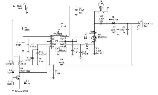
Figure 1 The SEPIC converter can use a single switch to buck or boost

The two 47 uH Coilcraft inductors in this circuit are: a very low leakage inductance (0.5 uH) MSD1260, and a higher leakage inductance (14 uH) MSC1278.
Figure 2 shows the primary current waveforms of these two inductors. The left side is the input current of the MSC1278 inductor (flowing into pin 1 of L1), and the right side is the MSD1260 input current waveform. The current on the left is a general case.
The current is mainly the DC of its triangular AC component. The waveform on the right is the result of using the high AC voltage of the coupled inductor and a low leakage inductance value. The peak current is almost twice the DC input current, and the RMS current is 50% more than the high leakage inductance case.
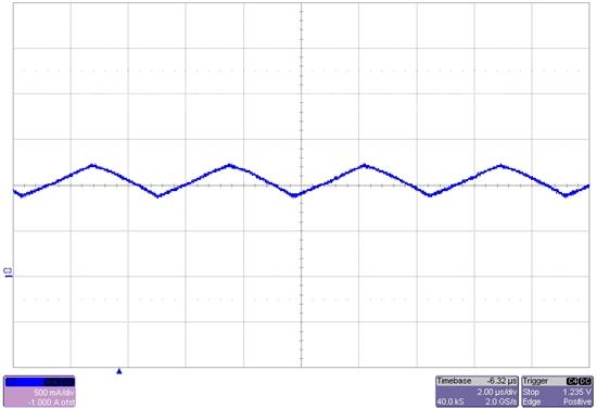
(a) Loosely coupled
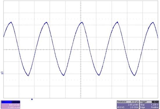
(b) Tightly coupled
Figure 2 Low leakage inductance (on the right) brings serious coupled inductor loop current

Obviously, using tightly coupled inductors for electromagnetic interference (EMI) filtering of such power supplies will have more problems. The AC input current ratio between these two designs is approximately 5:1, which means that an attenuation of 14 dB is required. The second effect of this high loop current is the effect on converter efficiency.
Since there is 50% more RMS current in the power supply, conduction losses will more than double. Figure 3 compares the efficiency of these two inductors (the rest of the circuit remains unchanged). When converting from 12V to 12V, both results are very good-both are around 90%. However, the efficiency of loosely coupled inductors is 1 to 2% higher in the load range, and its DC resistance is the same as that of tightly coupled inductors.
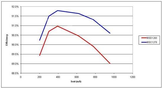
Figure 3 Due to less current, high leakage inductance (MSC1278) produces higher efficiency

In short, the coupled inductor in the SEPIC converter can reduce the size of the power supply and reduce the cost of the power supply. The inductors do not need to be tightly coupled. In fact, tight coupling increases the current in the power supply, which complicates input filtering and reduces efficiency. The easiest way to select the appropriate leakage inductance value is to use simulation. However, you can also estimate the voltage of the coupling capacitor first, then set the allowable ripple current, and finally calculate the minimum leakage inductance.