Several types of industrial systems (motor drives, solar and wind power inverters) and automotive systems (traction inverters) require accurate voltage and current measurements at high common-mode voltages. These voltage and current feedback signals are measured on the high-voltage side and transferred to the low-voltage side through some form of isolation.
As shown in Figure 1, a motor-drive system typically has two voltage domains: the “high-voltage” domain and the “low-voltage” domain. Such systems demand reliable galvanic isolation to isolate high-voltage circuits from low-voltage circuits. Typically, the voltage and current feedback signals measured on the high-voltage domain are galvanically isolated from the low-voltage domain with isolated amplifiers or isolated modulators. This dual-domain architecture protects human operators and prevents damage to expensive circuitry by breaking the ground loops between the high- and low- voltage circuits.


Figure 1: A dual-voltage domain architecture in motor drives. Click for a larger image (Source: Texas Instruments Inc.)
In this article, we will explain the concept of system voltage and working voltages, elaborate the standards driving the creepage and clearance requirements in several industrial and automotive systems, and highlight the key trends driving the need for higher creepage and clearance.
Understanding system and working voltages
The International Electrotechnical Commission (IEC) 60664-1 standard defines system voltage as a value based on the phase-to-ground or phase-to-phase voltage and the grounding scheme of the electrical distribution system. The system voltage determines the impulse voltage, which in turn determines the minimum clearance distance for the design. Working voltage is the maximum voltage referred to earth ground that occurs in the system and determines the creepage distance.
The supply grounding scheme plays an important role in determining isolation voltage levels. It is possible that two systems with an equal phase-to-phase supply voltage have significantly different system voltages, and therefore different creepage and clearance requirements. For example, a 690-VRMS Three-Phase, center-earthed system requires ≥8 mm of clearance and ≥5.4 mm of creepage for reinforced isolation, overvoltage category (OVC) III, pollution degree (PD) II, material group I, whereas a corner-earthed system with the same phase-to-phase voltage requires ≥14 mm of clearance and ≥10.8 mm of creepage.
TN and TT electrical distribution systems (definitions for TN and TT provided in IEC 60364-3) have one point in the system directly grounded – usually the star point of a three-phase generator or transformer. IT systems (definition for IT provided in IEC 60364-3) are less common and have no connection to ground at all. They are tolerant to ground faults and therefore found in safety-critical production environments such as chemical plants and mining operations. Corner-earthed systems are similar to IT systems with one phase grounded, and are common in industrial distribution networks.
Figure 2a shows a 690-V three-phase, center-earthed system in an electrical motor drive. The maximum rectified DC link voltage, including 10% variation of the nominal supply voltage, is 1,080 V (110% × 690 VRMS × Ö2) centered around neutral; the center point may connect to neutral. The maximum working voltage is ±540 V referred to earth ground. In the unearthed system shown in Figure 2b, the DC link voltage is also 1,080 V but is floating in respect to earth ground. In case of a ground fault (one of the three phases or DC+/DC– shorted to ground), the working voltage becomes the full 1,080 V. For this reason, IT and corner-earthed systems have higher system voltages and higher isolation distances compared to center-earthed systems.


Figure 2: 690-V three-phase, center-earthed TN or TT system (left); unearthed IT system (right). Click for a larger image. (Source: Texas Instruments Inc.)
Understanding creepage and clearance requirements
While designing high-voltage systems, you need to consider the relevant safety standards and requirements – working and transient voltages, pollution degree, altitude, isolation type, and material group – to determine the minimum creepage and clearance requirements for isolation.
In a motor-drive system, the isolation requirements are more stringent because of high operational voltages and interfaces accessible to human operators. You must check the isolation between the high- and low-voltage parts of the system against the requirements of the IEC 61800-5-1 standard for electrical power drive systems, and design isolation to withstand the rated impulse voltage, temporary overvoltage, and working voltage. In addition, the physical distance between exposed metal parts on the high- and low-voltage sides must meet the minimum creepage and clearance requirements.
Understanding altitude
At higher altitudes, the air pressure is lower than at sea level. A peak overvoltage such as a surge or temporary overvoltage can more readily cause arcing between the isolator pins. The IEC 61800-5-1 standard provides multiplication factors by which you must increase the clearance at altitudes above 2,000 meters (m) to prevent arcing. As an example, if a motor drive system is designed to operate at altitudes as high as 5,000 m, you would multiply the minimum clearance by a factor of 1.48.
Understanding pollution degree
Pollution degree is the amount of dry pollution and condensation present in the environment. There are four classification levels, level I through level IV, based on the conductivity of pollution. This classification affects the creepage and clearance requirements of isolation products. For example, continuous operation in heavy pollution can cause tracking – when package surfaces degrade and create a conductive path across the isolation. In such cases, a higher-quality packaging mold compound that belongs to a lower material group with a higher comparative tracking index is necessary, or you will need to increase the minimum creepage distance. A typical motor-drive system is designed for pollution degree level II.
Understanding clearance
As shown in Figure 3, clearance is the shortest distance between two conductive materials through air. The clearance distance does not need to be a straight line. On many occasions, the shortest path between exposed leads is along the surface of the package, and clearance becomes equal to creepage. You can learn more about this topic in the video, “Isolation: What are Creepage and Clearance?”
Table B.1 of the IEC 60664-1 standard defines the impulse voltage for a 690-V three-phase unearthed system (such as an IT system, OVC III) as 8,000 V peak to peak. This table also defines the system voltage of a 690-V, three-phase IT system as 1,000 VRMS. According to Table 9 in IEC 61800-5-1, the minimum clearance for an 8,000 peak-to-peak impulse voltage is 14 mm for reinforced isolation.


Figure 3: Definition of clearance. Click for a larger image. (Source: Texas Instruments Inc.)
Understanding creepage
Creepage, as shown in Figure 4, is the shortest path between two conductive materials along the surface of an isolator. As an example, according to Table 10 in IEC 61800-5-1, the minimum creepage distance for a working voltage of 1,080 VRMS, insulating material group I, pollution degree II, and reinforced isolation is 10.8 mm.


Figure 4: Definition of creepage. Click for a larger image. (Source: Texas Instruments)
Table 1 summarizes the maximum surge isolation voltage (VIOSM), the maximum transient isolation voltage (VIOTM), and the clearance and creepage requirements for reinforced isolation in a motor-drive system using IEC 60664-1 and IEC 61800-5-1.

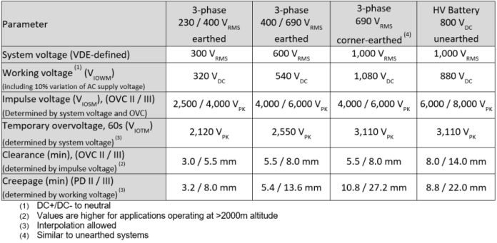
Table 1: Creepage and clearance requirements in motor drives using IEC 60664-1 and IEC 61800-5-1. Click for a larger image. (Texas Instruments Inc.)
In a photovoltaic system such as solar power converter, IEC 62109-1 is the safety standard for solar power converters. This standard defines the minimum requirements for protection in these systems against electric shock, energy, fire, mechanical or other hazards. IEC 62109-1 provides transient overvoltage, impulse voltage, working voltage, creepage, and clearance requirements for these photo-voltaic systems.
In medical equipment, IEC 60601-1-2 (fourth edition) is the safety standard used to determine isolation voltage and transient overvoltage capabilities. This standard calls for ±8 kV for contact discharges and ±15 kV for air discharge levels between the sensing circuitry and direct patient or user contact to the microcontroller. This safety standard determines isolation and creepage specifications.
Future trends driving the need for higher isolation ratings in isolation products
The operating working voltages in industrial systems such as motor drives, solar and wind power inverters, and automotive systems such as traction inverters, are increasing for several reasons – to increase output power, or to improve overall efficiency or to reduce cost. Higher DC bus voltages enable higher power ratings without increasing current levels, thereby reducing the per-unit cost of energy generated. Also, higher voltages increase efficiency because the total power output can increase, and when currents do not change, the conduction losses remain the same.
In a photovoltaic system such as a solar inverter, there is a trend to upgrade designs from 1,000 VDC voltages to 1,500 VDC voltages to reap the benefits realized by increased DC bus voltages. The IEC 62109-2 standard addresses potential electrical hazards associated with increased voltages in these systems.
In a motor-drive system, IEC 61800-5-1 addresses potential electrical hazards. Higher-voltage grids such as 690 VRMS are cost-effective to install and operate, and are popular in high-power industrial environments.
In electric vehicles, the priority is to increase battery voltages to lower system weight, reduce charging times, and increase range.
As these trends continue to proliferate in industrial and automotive markets, reinforced isolation amplifiers such as the AMC1411 from Texas Instruments – offered in a stretched small-outline integrated circuit (SOIC) package with ≥14.7 mm of clearance and ≥15.7 mm of creepage – provide a cost-effective high-performance solution for isolated voltage and current sensing. The AMC1411 offers 10,600 VPK-PK reinforced isolation in compliance with VDE[1] V 0884-11 (VIOTM) and 7,500-VRMS isolation for 1 minute per UL[2] 1577. The amplifier’s high isolation voltage ratings and high common-mode transient immunity of 100 kV/µs ensure reliable and accurate operation even in harsh industrial and automotive environments.
[1] Deutsches Institut für Normung Verband der Elektrotechnik, Elektronik und Informationstechnik
[2] Underwriters Laboratories
about Texas Instruments