So we’ve just started another exciting job in Analog IC design at a good company. We pat ourselves on the back and feel proud of ourselves until a design problem hits our desk. We jump in with both our feet and, lo and behold, what our manager told us was a week’s worth of work has turned out to be much longer.
Sound familiar? I suppose I’m not the first, as others must have encountered the same thing. Consider the graph below:
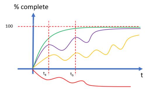

If we plot percentage complete on the y axis and time on the x axis, and sketch out how long it will take to complete a given task, ideally, we end up with the green curve. The green curve can be defined by a simple equation;
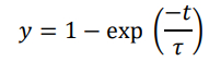
Where t is time and T is the time constant, which is a measure of efficiency.

However, in the case where we get stuck in a problem, consider the purple graph. Here, we start off well and rapidly get to a point where we stall. We seem to have hit a snag, until eventually we find our way out of it, by sheer determination and tenacity. We proceed along this trajectory until we hit another snag and so and so forth. Eventually the task is completed but not until we have experienced the snags, or what I call “problem traps”.
In the red graph, the problem traps are so severe the task simply doesn’t complete and diverges from the required solution. In this case, the activity needs to stop and start again.
Let’s look at a simple example. The diagram below of a simple common emitter amplifier.
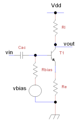
Suppose we set the voltage drop across Re to approximately 0.1V, so I adjust the dc voltage vbias until the voltage across the emitter is 0.1V. Assuming I wanted to achieve a gain of 30dB or x32, and I set Re=100 ohms, which means the tail current is 1mA. This means re=VT/I, VT=25mV, I=1ma, re=25 ohms. So now I want to work out Rl, so
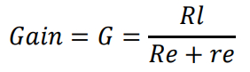
Setting G=32, Re=100, re=25, gives Rl=4k!


Now if I set Vdd=3V, the voltage on the collector of T1 is -1V, the base collector junction is forward biased so I’m not likely to see much gain from this, however, if I blindly build the design, I will be traversing along the purple line. Another issue could be the choice of Rbias. Let’s assume that the source impedance driving Cac is 1k and I set Rbias to 1k. Well in that case, I have to ensure the signal I drive into the base is at least twice as big to achieve 30dB gain. But if I accidentally set Rbias to 10 ohms, I’m attenuating the signal directly at the input. Perhaps I captured the schematic on the CAD tool and accidentally left Rbias at 10 ohms and then I run a simulation to check my gain is way lower than expected. I scratch my head….no joy.
I keep simulating without thinking about the parameters in the design…..so I’ve now hit another snag. Eventually, one of my friendly colleagues walks past and notices Rbias is set to 10 ohms….will they point out my silly mistake?
This is all very well for well understood mathematics and simple circuits. Life isn’t that simple and I believe problem traps still occur. When designing at much higher frequencies, say ft/8, we can no longer assume dc values of beta. So when our circuit doesn’t work, it’s not because of something obvious, but rather we have missed something…a problem trap.
Consider the two stage amplifier shown below:
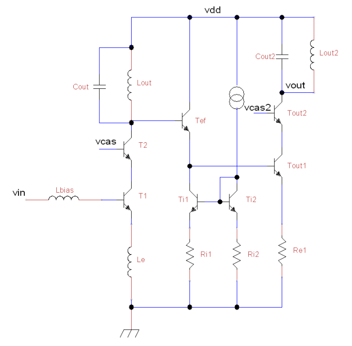
If we had assumed beta was a dc value, we would’ve neglected the effect of β2.Re1 where, β2 =
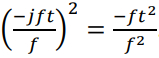
In other words, a negative resistance which will appear across the tuned load Lout and Cout. This could have a detrimental effect on stability of the amplifier and oscillate. We wouldn’t have noticed that until we ran, say, a transient, if Re1 was badly chosen….another problem trap. In this situation, we may have ended up with the red graph which is spiralling away from 100% complete and moving towards the negative direction….ie design problem will never complete.


If we had planned around this, we would have first thought, do we really need Tef and connected the output stage directly to the input stage by ac coupling. This way, I can bias the output stage independently and not have to worry about a negative impedance. Well, not quite because there will be a parasitic capacitance at the emitter of Tout1.
In this case, the parasitic cap will appear as a negative impedance across Lout//Cout….again we need to look out for these effects.
Perspectives
Harriet Green says, citing Wayne Schaefer (Even the Finest Engineers Can Experience Confirmation Bias):
“It’s been my experience that making stuff can be complicated! Even the most advanced, well-managed production environments will experience manufacturing problems on an ongoing basis. Some of these will be simple and have an obvious, quick solution while others will require rigorous exploration to uncover the root cause. ”
“One thing that shouldn’t change, however, is how engineers approach manufacturing, maintenance, design and shop floor problems. I think it’s key to consider carefully all of the potential causes and solutions before arriving at a conclusion. As data is collected and analysed, initial solutions can inadvertently be favoured over more correct options. What Wayne talks about is ‘confirmation bias’, this involves knowingly or unknowingly liking more information that supports preconceived ideas while ignoring or discrediting data that contradicts them. It’s a common and often subconscious tendency, which makes it extremely important for engineers to be aware of this bias in my humble experience.”
“Every effort must be made to consider the totality of perspectives, causes and solutions to arrive at the best outcome for a given problem while avoiding suboptimal results and continued or recurring malfunctions. The tendency to favor or fixate on one particular solution can only be overcome using solid problem-solving tools and methodology.Various tools can be deployed depending on the nature of the problem, the desired outcome and the resources available. One example, the Red X process, helps avoid confirmation bias in a variety of ways. Red X, developed by Dorian Shainin, refers to the dominant root cause shown as a color-coded red on a chart that prioritizes what is observed to have the greatest effect on the quality of a process (also known as a Pareto chart).”
As Harriet outlines, rather than jumping into solving the problem, it is better to plan the work in advance, so that problem traps can be avoided as much as possible.
Gareth Jones
Another perspective comes from Gareth Jones, Garfield Microelectronics’s Projects Director. He says the following, regarding problem traps:
“As part of GF Micro’s full offering of silicon design services and silicon supply, our design process looks at potential problem traps early on in the project lifecycle before any design work is started. This evaluation takes the form of a feasibility study where we investigate the pros and cons of the customer specification and our proposed design architectures and then evaluate the risk associated with each proposal.”
“By taking this approach, it allows GF Micro to have a better understanding of possible issues and put in place mitigation plans to reduce the impact of problem traps. Post feasibility study, where we are working on the full design development, there are still likely to be problem traps but the severity of these issues is diminished due to the previous planning undertaken. This allows us to stay closer to the ideal problem trap green curve, thereby reducing the likely impact to the overall project schedule.”
Mark Thackeray
Mark Thackeray is a renowned businessman and has been a Project Director/Manager for years, deploying enterprise software to some of the world’s largest companies.
Problem traps occur when teams, products and timelines are not alighted, communication in project management is essential to prevent failure, one way Mark resolved problem traps is through the use of Visual Management, a solution designed to align all parties to any issues quickly and define a resolution roadmap.
Plan not jump
In summary, problem traps occur in all aspects of engineering and we need to be aware of them, so that we can plan around them.
Moving into a new design space with little experience, we are likely to traverse the purple line, but in time we will get there. The point I’m trying to make here is that we plan our work as best we can before we jump in.
Author


He has worked from a number of big companies, such as Ferranti, STL, GEC Plessey Semiconductors, Maxim Integrated, Dialog Semiconductors, to name a few. He has also worked in startups, such as Phyworks. During his tenure at GEC Plessey Semiconductors, Ash raised over 20 patents, including Synthesis Exploiting Algebraic Design, which was used successfully in a number of products.
For relaxation, Ash enjoys running, walking, spending time with his wife, daughters and grandchildren. Ash is also active as a composer both in Chamber and Orchestral works.
See also: Viewpoint: From BC108 to SiGe BiCMOS – why Analog ICs are great
View more : IGBT modules | LCD displays | Electronic Components