Fuji Electric 1DI100MA-050: A Technical Review of the 500V 100A Transistor Module
“`html
1DI100MA-050 Fuji Electric Transistor Module | 500V 100A
Introduction & Core Highlights
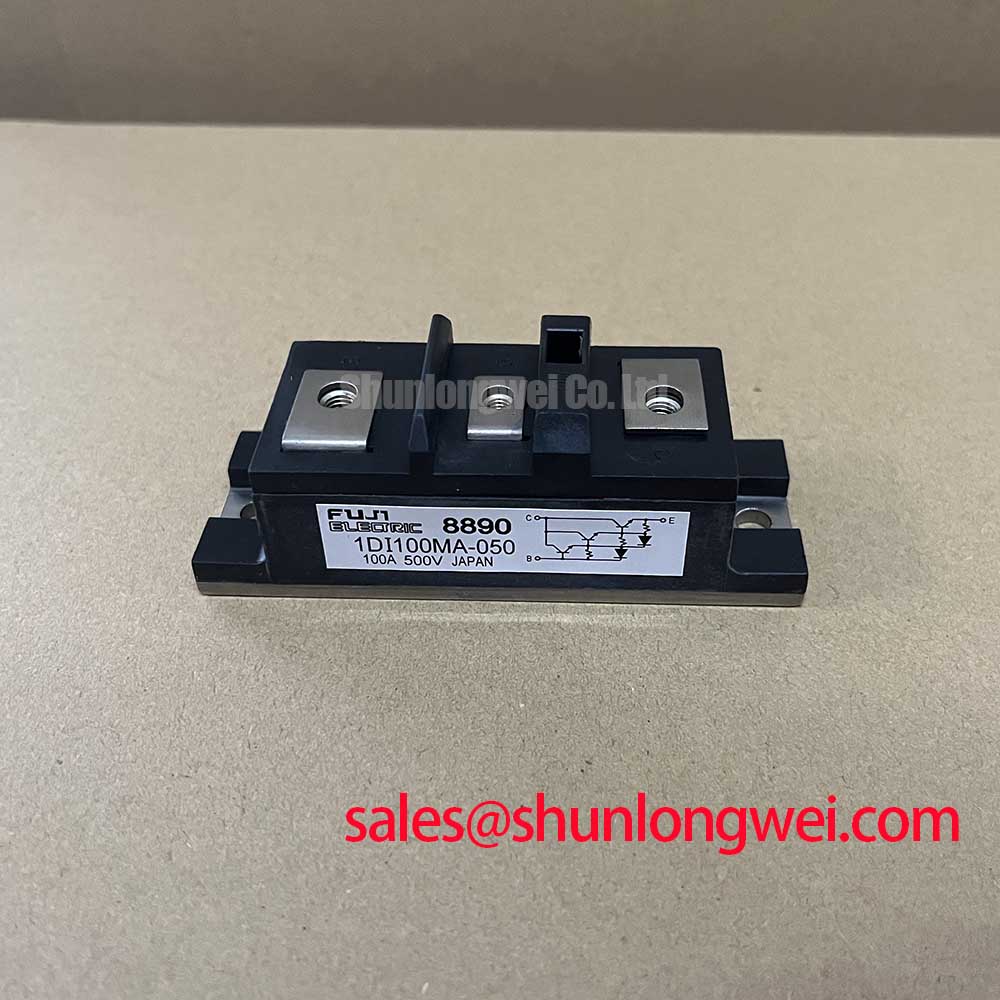
The Fuji Electric 1DI100MA-050 is a high-current transistor module that integrates a single NPN transistor and a parallel freewheeling diode into a compact, isolated package. This module is engineered for power conversion systems that demand robust performance and straightforward thermal management. Its electrical and thermal characteristics are specified to support reliable operation under high-current conditions, making it a functional component for various industrial switching applications.
- Core Specifications: 500V | 100A | VCE(sat) 2.5V (max)
- Key Strengths: Isolated mounting base for simplified assembly, well-defined thermal resistance for predictable heatsink design.
- Design Consideration: The module’s maximum collector-emitter saturation voltage (VCE(sat)) is a critical parameter for calculating conduction losses and subsequent cooling requirements.
Download the Official 1DI100MA-050 Datasheet (PDF)

Technical Analysis of Key Parameters
A central characteristic of the 1DI100MA-050 is its collector-emitter saturation voltage, VCE(sat), specified at a maximum of 2.5V at the rated collector current of 100A. This value is fundamental to system efficiency, as it directly determines the power dissipated as heat during the transistor’s on-state (P_loss = VCE(sat) × I_C). A lower VCE(sat) translates to reduced conduction losses, which in turn simplifies the thermal management strategy and can lead to smaller heatsink requirements.
The module’s thermal resistance from junction to case (Rth(j-c)) is documented as 0.28°C/W for the transistor and 0.5°C/W for the freewheeling diode. This parameter is analogous to the width of a pipe for heat flow; a lower value signifies a wider pipe, allowing heat to escape more effectively from the semiconductor junction to the heatsink. These defined values are essential for engineers performing thermal calculations to ensure the maximum junction temperature of 150°C is not exceeded, a cornerstone of designing for long-term reliability in power semiconductors.
Optimized Application Scenarios
The 1DI100MA-050’s specifications make it suitable for several high-power applications:
- AC Motor Controls: Its 100A current rating is well-suited for driving medium-sized induction motors, where the low VCE(sat) helps minimize losses in the inverter stage.
- Welding Power Supplies: The module can handle the high current pulses required in welding applications, with the freewheeling diode providing a necessary path for inductive current.
- DC Choppers & High Power Switching: For general-purpose power conversion, the device serves as a robust switching element capable of managing significant energy throughput.
- Uninterruptible Power Supplies (UPS): Its reliable switching performance is valuable for the inverter and converter stages within a UPS system.
Its robust current handling and defined thermal characteristics make it a best match for industrial systems requiring reliable, high-current switching components.
Key Specification Parameters for 1DI100MA-050
| Parameter | Symbol | Condition | Value | Unit |
|---|---|---|---|---|
| Absolute Maximum Ratings (Tc=25°C) | ||||
| Collector-Emitter Voltage | V_CES | – | 500 | V |
| Gate-Emitter Voltage | V_GES | – | ±20 | V |
| Collector Current (DC) | I_C | – | 100 | A |
| Collector Current (Pulsed) | I_CP | 1ms pulse | 200 | A |
| Max Power Dissipation | P_C | – | 440 | W |
| Electrical Characteristics (Tj=25°C) | ||||
| Collector-Emitter Saturation Voltage | V_CE(sat) | I_C=100A, V_GE=15V | 2.5 (Max) | V |
| Gate-Emitter Threshold Voltage | V_GE(th) | V_CE=10V, I_C=100mA | 4.0 – 8.0 | V |
| Collector Cut-off Current | I_CES | V_CE=500V | 2.0 (Max) | mA |
| Thermal Characteristics | ||||
| Thermal Resistance (Transistor) | Rth(j-c) | Junction to Case | 0.28 (Max) | °C/W |
| Thermal Resistance (Diode) | Rth(j-c) | Junction to Case | 0.5 (Max) | °C/W |
| Operating Junction Temperature | Tj | – | -40 to +150 | °C |
Engineer’s FAQ
1. How is the required heatsink thermal resistance calculated for the 1DI100MA-050?
To determine the required heatsink performance, first calculate the total power dissipation (P_D). Then, use the formula: Rth(c-a) = (Tj_max – Ta) / P_D – Rth(j-c). Where Tj_max is 150°C, Ta is the ambient temperature, P_D is the total power dissipation, and Rth(j-c) is 0.28°C/W for the transistor. Ensure to account for the thermal resistance of any interface material.
2. What are the recommended mounting torque settings?
According to the datasheet’s outline drawing, the recommended torque for the main terminal screws (M5) is 2.5 to 3.5 N·m. For the module mounting screws (M6), the recommended torque is 3.0 to 4.0 N·m. Applying the correct torque is critical for ensuring low thermal and electrical contact resistance.
3. What is the purpose of the integrated freewheeling diode (FWD)?
The FWD provides a safe path for current to flow when the transistor is turned off in systems with inductive loads, such as electric motors. This prevents a large voltage spike across the transistor, protecting it from damage. The FWD in the 1DI100MA-050 has a maximum forward voltage (V_F) of 2.5V.
Enabling Robust Power Designs
For industrial systems requiring a high-current, 500V switching component, the 1DI100MA-050 offers a practical solution. Its integration of a transistor and diode in an isolated package, combined with clear specifications for thermal performance, provides engineers with the necessary elements to build efficient and reliable motor drives, power converters, and welding systems.
“`