Mitsubishi CM150DU-24F IGBT: A Technical Review and Application Guide
Mitsubishi CM150DU-24F IGBT Module | 1200V 150A Dual
Introduction and Core Highlights
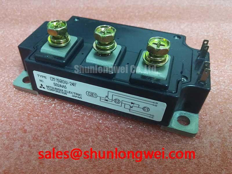
The Mitsubishi CM150DU-24F is a dual IGBT module from the F-Series, providing a robust and efficient solution for high-power switching applications. Its core value is delivering a balanced combination of low conduction losses and dependable thermal performance within a standard industrial package. This allows engineers to design systems with simplified thermal management. The module’s well-defined thermal resistance characteristics are crucial for accurately calculating heatsink requirements, ensuring reliable operation under load.
- Core Specifications: 1200V | 150A | VCE(sat) 2.2V (typ)
- Key Advantages: Low on-state voltage minimizes heat generation, and the industry-standard housing simplifies mechanical assembly.
Download the Official CM150DU-24F Datasheet (PDF)
Technical Analysis for System Integration
A key performance metric of the CM150DU-24F is its low collector-emitter saturation voltage (VCE(sat)), specified at a typical value of 2.2V at its nominal 150A current (Tj=125°C). This parameter is a direct indicator of the power lost as heat while the IGBT is in its ‘on’ state. A lower VCE(sat) value directly contributes to higher overall inverter efficiency and reduces the thermal burden on the cooling system, potentially allowing for a smaller, more cost-effective heatsink design.
Effective thermal management is enabled by the module’s clearly specified thermal resistance. Think of thermal resistance (Rth(j-c)) as the width of a pipe for heat to escape; a lower value means heat can flow out more easily. The datasheet provides distinct Rth(j-c) values for the IGBT (0.16°C/W) and the free-wheeling diode (0.30°C/W). This level of detail allows engineers to perform precise thermal simulations, ensuring the device’s junction temperature remains well within the maximum limit of 150°C during operation. For further reading, consult resources on mastering IGBT thermal design.
Optimized Application Scenarios
The electrical and thermal characteristics of the CM150DU-24F make it a strong candidate for a range of industrial applications:
- Variable Frequency Drives (VFDs): The 1200V blocking voltage and 150A current rating are ideal for the inverter stage of AC motor drives operating on 380-480V mains.
- Uninterruptible Power Supplies (UPS): Its dual configuration simplifies the design of H-bridge or half-bridge topologies used in high-availability power backup systems.
- Industrial Welding Equipment: The module’s ability to handle high pulse currents (ICP up to 300A) makes it suitable for the demanding switching requirements of welding power sources.
- Solar Inverters: A reliable component for the DC-AC conversion stage in grid-tied solar power systems, where efficiency and longevity are critical.
This module provides an optimal balance of performance and reliability for power converters in the 45kW to 75kW range.
Key Specifications of the CM150DU-24F
| Absolute Maximum Ratings (Tj = 25°C unless otherwise noted) | |
|---|---|
| Collector-Emitter Voltage (VCES) | 1200V |
| Gate-Emitter Voltage (VGES) | ±20V |
| Collector Current (IC) | 150A |
| Maximum Power Dissipation (Pc) | 600W |
| Electrical & Thermal Characteristics (Tj = 125°C unless otherwise noted) | |
| Collector-Emitter Saturation Voltage (VCE(sat)) @ 150A | 2.2V (typ), 2.7V (max) |
| Emitter-Collector Voltage (VEC) @ 150A | 2.3V (typ), 2.8V (max) |
| Thermal Resistance, Junction to Case (Rth(j-c)) – IGBT | 0.16°C/W (max) |
| Thermal Resistance, Junction to Case (Rth(j-c)) – Diode | 0.30°C/W (max) |
Engineer’s FAQ for the CM150DU-24F
1. What is the key consideration for designing a heatsink for the CM150DU-24F?
The most critical factor is the maximum thermal resistance (Rth(c-f)) between the module’s case and the heatsink. To maintain the junction temperature below the 150°C maximum, you must calculate total power losses (conduction and switching) and use the Rth(j-c) values from the datasheet to determine the required case-to-ambient thermal resistance of your cooling solution.
2. What is the recommended mounting torque for this module?
The datasheet specifies a mounting torque for the main terminal screws (M5) and the mounting screws (M6). Adhering to these values (typically 2.5-3.5 N·m for M5 and 3.5-4.5 N·m for M6) is vital to ensure proper electrical and thermal contact without causing mechanical stress to the module. Always use a calibrated torque wrench.
3. The datasheet lists both IC (150A) and ICP (300A). How does this apply to a motor drive application?
IC is the continuous DC collector current the device can handle. ICP is the peak repetitive pulse current, which it can handle for short durations (specified as 1ms in the datasheet). In a motor drive, IC relates to the nominal running current, while ICP is relevant for handling transient events like motor startup, acceleration, or sudden load changes.
4. Does this module contain an integrated temperature sensor?
No, the CM150DU-24F does not include an internal NTC thermistor. For designs that require real-time temperature monitoring, an external sensor must be placed near the module’s baseplate. Understanding the importance of this feature can be explored in our guide to the role of an integrated NTC for IGBT module safety.
Design Enablement
The CM150DU-24F provides a straightforward path for developing efficient and durable power conversion systems. Its industry-standard footprint, combined with a data-centric specification sheet, gives engineers the necessary tools to implement a half-bridge topology with predictable thermal and electrical behavior, directly supporting goals for system longevity and performance.