Infineon FF200R12KS4 (1200V, 200A) IGBT Module: A Technical Review
Infineon FF200R12KS4 Dual IGBT Module | 1200V 200A
Technical Analysis of the FF200R12KS4 for Power Systems
The Infineon FF200R12KS4 is a 1200V, 200A dual IGBT module that leverages TrenchStop® IGBT3 technology to deliver a balanced performance for industrial power conversion. Housed in the industry-standard EconoDUAL™ 3 package, it provides a robust and efficient solution by focusing on minimizing conduction losses and ensuring reliable switching behavior. This module is engineered for systems where thermal performance and operational durability are key design considerations.
- Core Specifications: 1200V | 200A | VCE(sat) 1.70V (typ. at 25°C)
- Key Advantages: Low conduction losses improve thermal efficiency; Emitter Controlled Diode ensures soft switching and reduced EMI.
- Design Focus: The low collector-emitter saturation voltage (VCE(sat)) directly reduces the heat generated during operation, simplifying thermal management requirements.
Download the Official FF200R12KS4 Datasheet (PDF)
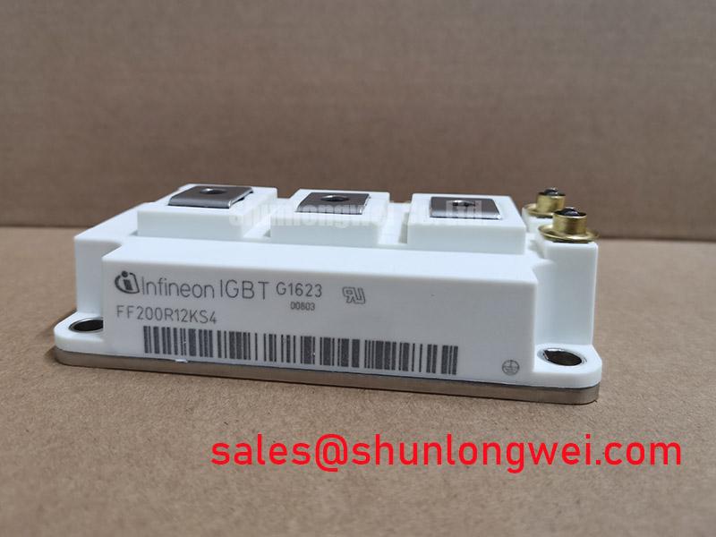

A Deeper Look at Technical Performance
The engineering value of the FF200R12KS4 is centered on its core silicon and packaging. The use of Infineon’s TrenchStop™ IGBT3 technology is fundamental to achieving a low VCE(sat) of 1.70V (typical at 25°C, 200A). This parameter is critical for system efficiency. Think of VCE(sat) as the resistance of a water valve when it’s fully open; a lower value means less pressure is lost, or in this case, less energy is wasted as heat while current flows. This directly reduces the thermal load on the heatsink, enabling more compact and cost-effective cooling solutions. For a comprehensive understanding of IGBT thermal behavior, refer to this guide on mastering IGBT thermal design.
Complementing the IGBT is an integrated Emitter Controlled Diode. This freewheeling diode is engineered for soft recovery characteristics. During the switching process, a soft-recovery diode helps to prevent large voltage overshoots and high-frequency oscillations. This behavior significantly reduces electromagnetic interference (EMI), which can simplify the system’s filtering requirements and contribute to overall stability. The module is specified for a robust short-circuit withstand time of 10 µs, providing a critical safety margin in fault conditions. This level of protection is essential for preventing catastrophic device failure, a topic further explored in our analysis of IGBT failure modes.
Optimized Application Scenarios
The FF200R12KS4’s feature set makes it highly suitable for a range of demanding power semiconductor applications:
- Motor Drives: The low VCE(sat) is highly advantageous in variable frequency drives (VFDs), where conduction losses at lower switching frequencies are a dominant factor in overall efficiency.
- Uninterruptible Power Supplies (UPS): Its high short-circuit robustness and reliable performance within the standard EconoDUAL™ 3 package are critical for ensuring uptime in mission-critical UPS systems.
- Solar Inverters: The balance between low conduction losses and moderate switching losses helps maximize energy conversion efficiency in central solar inverters.
- Welding and Induction Heating: These applications demand robust components that can handle high current pulses. The 200A nominal rating and well-defined Safe Operating Area (SOA) of the FF200R12KS4 meet these requirements.
This module provides an excellent balance for industrial power systems requiring high efficiency and proven reliability without aggressive switching frequencies.
Key Specifications of the FF200R12KS4
| Parameter | Symbol | Conditions | Value |
|---|---|---|---|
| Absolute Maximum Ratings | |||
| Collector-Emitter Voltage | V_CES | T_vj = 25°C | 1200 V |
| Nominal Collector Current | I_C nom | T_C = 80°C | 200 A |
| Short Circuit Withstand Time | t_psc | V_GE ≤ 15V, V_CC = 800V, T_vj ≤ 150°C | 10 µs |
| IGBT Characteristics (T_vj = 125°C unless otherwise specified) | |||
| Collector-Emitter Saturation Voltage | V_CE(sat) | I_C = 200A, V_GE = 15V | 2.05 V (typ.) |
| Gate Threshold Voltage | V_GE(th) | I_C = 8.0 mA, T_vj = 25°C | 5.0V to 6.5V |
| Thermal & Mechanical Characteristics | |||
| Thermal Resistance, Junction-to-Case | R_thJC | per IGBT | 0.085 K/W |
| Thermal Resistance, Junction-to-Case | R_thJC | per Diode | 0.140 K/W |
| Operating Junction Temperature | T_vj op | – | -40 to +150 °C |
| Mounting Torque | M | Mounting screw M5 | 3.0 – 6.0 Nm |
Note: All specifications are based on the official Infineon FF200R12KS4 datasheet. Verification by the design engineer is recommended.
Engineer’s FAQ for FF200R12KS4
How does the VCE(sat) of 2.05V at 125°C impact thermal design?
This value is a primary input for calculating conduction losses (P_cond = VCE(sat) × I_C × Duty Cycle). At a continuous current of 200A, this results in significant power dissipation as heat. Your thermal design, including the heatsink and airflow, must be sufficient to keep the junction temperature below the 150°C maximum rating under worst-case operating conditions.
What are the key considerations for mounting the EconoDUAL™ 3 package?
Proper mounting is crucial for effective heat dissipation. The datasheet specifies a mounting screw (M5) torque between 3.0 and 6.0 Nm. It is essential to apply a uniform layer of thermal interface material (TIM) to the module’s baseplate to minimize thermal resistance between the module and the heatsink (R_thCH). Uneven torque or improper TIM application can create hot spots and compromise reliability.
What is the function of the integrated NTC thermistor?
The built-in NTC thermistor provides a means for real-time temperature monitoring of the module’s baseplate. This feedback is critical for the system’s control logic, allowing it to implement thermal protection schemes like power derating or emergency shutdown if the temperature exceeds safe limits, thereby enhancing system longevity.
Is the FF200R12KS4 suitable for high-frequency switching applications?
The FF200R12KS4 uses TrenchStop® IGBT3 technology, which is optimized for a balance between low conduction losses and moderate switching losses. While suitable for many motor drives and UPS systems operating in the low-to-mid kilohertz range, it is not intended for very high-frequency applications (e.g., >20-30 kHz), where newer technologies like IGBT4 or SiC would typically offer lower switching losses.
Design Enablement
The FF200R12KS4 provides a technically sound basis for developing industrial power converters. Its integration of low-loss TrenchStop® IGBT3 technology with robust thermal characteristics in a widely adopted package empowers engineers to create efficient and reliable systems. The module’s performance characteristics are well-defined, offering a predictable and dependable component for demanding power applications.