QM100DY-H: A Technical Analysis of a High-Gain, Isolated Darlington Module
QM100DY-H | 600V 100A Dual Darlington Transistor Module
Introduction and Core Highlights
The Mitsubishi QM100DY-H is a dual Darlington transistor module delivering high DC current gain (hFE) and robust 2500V isolation in a single package. This design simplifies the drive circuitry and enhances safety for medium-power switching applications. By integrating two transistors, it streamlines the construction of inverter and chopper circuits, while its isolated baseplate simplifies thermal management and mechanical assembly onto a heatsink.
- Core Specifications: 600V | 100A | hFE 75 (typ)
- Key Advantages: High gain reduces drive circuit complexity; integrated 2500V isolation enhances system safety and reliability.
Download Official Datasheet (PDF)
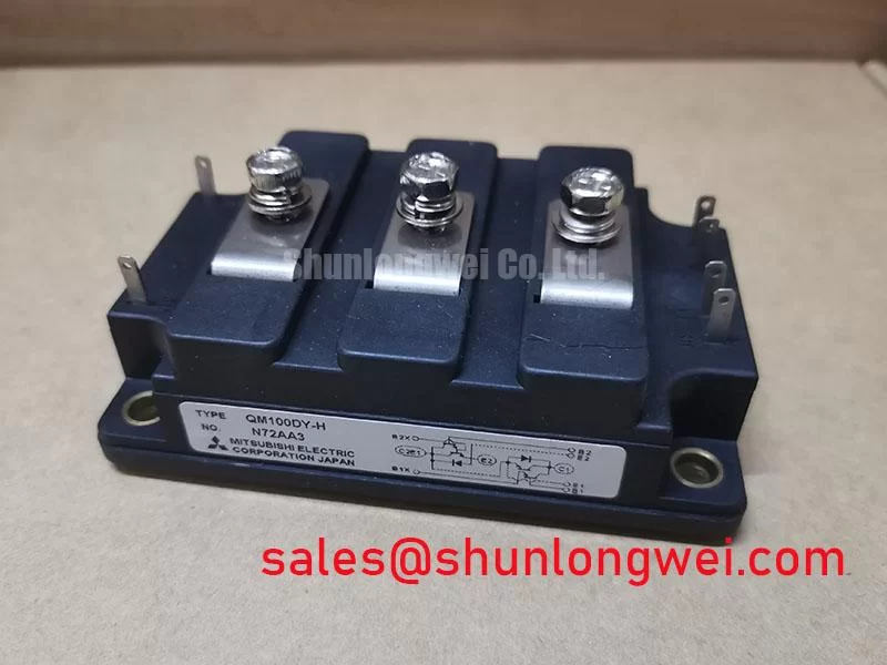

Technical Analysis: High Gain and Isolation
A primary engineering benefit of the QM100DY-H module is its high DC current gain (hFE), specified with a typical value of 75 at a 100A collector current. This performance is achieved through its Darlington pair configuration, where two bipolar junction transistors are cascaded. The result is that a small base current can effectively control a much larger collector current. For system designers, this translates directly to a less complex and lower-power drive circuit, reducing component count and potential points of failure when compared to driving a single high-power BJT.
The module features an integrated baseplate that provides 2500V (AC for 1 minute) of electrical isolation between the active semiconductor elements and the mounting surface. This is crucial for both safety and design simplification. Think of the module’s baseplate as a secure electrical barrier; it allows heat to pass through to the heatsink efficiently while preventing dangerous high voltages from reaching the mounting structure. This eliminates the need for external insulating pads, which can increase thermal resistance and assembly complexity. The result is a more reliable thermal management path and a safer overall system.


Optimized Application Scenarios
The characteristics of the QM100DY-H make it a suitable component for specific industrial power systems. Its robust design and electrical specifications are aligned with the demands of the following applications:
- AC and DC Motor Controllers: The dual-transistor configuration is structured for building half-bridge topologies, which are fundamental blocks for motor inverters and choppers.
- Welding Power Supplies: The module’s ability to handle a peak collector current of 1000A (60Hz half-wave) makes it resilient enough for the pulsed power demands of welding applications.
- High-Power Switching Regulators: For linear or switching power supplies, its 100A continuous current rating provides ample capacity for high-output designs.
- Servo Drives and NC Equipment: The high gain and reliable switching performance support the precise control required in numerical control (NC) machines and servo systems.
Its combination of high gain, robust current handling, and integrated isolation makes it a strong match for medium-frequency power conversion systems requiring simplified control circuits.
Key Specification Parameters
| Absolute Maximum Ratings (Tj=25°C) | ||
|---|---|---|
| Collector-Emitter Voltage (VCEX) | 600V | |
| Collector Current (IC) | 100A | |
| Collector Power Dissipation (PC) | 620W | |
| Junction Temperature (Tj) | -40 to +150°C | |
| Electrical Characteristics (Tj=25°C) | ||
| Collector-Emitter Saturation Voltage (VCE(sat)) | 2.5V (Max) @ IC=100A, IB=1.3A | |
| DC Current Gain (hFE) | 75 / 100 (Typ/Min) @ IC=100A, VCE=2V/5V | |
| Turn-On Time (ton) | 5.0µs (Typ) | |
| Turn-Off Time (toff) | 15.0µs (Typ) | |
| Thermal & Mechanical Characteristics | ||
| Thermal Resistance (Rth(j-c)Q) | 0.2°C/W (Per Transistor) | |
| Isolation Voltage (Viso) | 2500V (AC, 1 min.) | |
| Mounting Torque | 1.47 – 1.96 N·m (M5 Screw) | |
Engineer’s FAQ
How do I calculate the heatsink requirement for the QM100DY-H?
To determine the required heatsink, you must manage the total thermal resistance from the semiconductor junction to the ambient air. The datasheet specifies the junction-to-case thermal resistance (Rth(j-c)) as 0.2°C/W per transistor. You must also account for the case-to-fin thermal resistance (Rth(c-f)), which is typically 0.05°C/W with thermal grease. The total allowable temperature rise (Tj(max) – Tambient) divided by the power dissipation (Pd) gives the maximum total thermal resistance. The heatsink’s resistance will be the remainder: Rth(f-a) = Rth(total) – Rth(j-c) – Rth(c-f).
What is the recommended mounting torque for this module?
The datasheet specifies a mounting torque of 1.47 to 1.96 N·m for the M5 mounting screws. Adhering to this specification is critical. Insufficient torque leads to poor contact between the module baseplate and the heatsink, increasing thermal resistance and causing overheating. Excessive torque can warp the baseplate, leading to mechanical stress and premature device failure.
How does this Darlington module compare to a modern IGBT?
This Darlington module offers very high current gain (hFE), which simplifies the drive circuit. However, it has a higher collector-emitter saturation voltage (VCE(sat)) of up to 2.5V, leading to higher conduction losses compared to a modern Trench Gate IGBT. Darlingtons also typically have slower switching speeds (turn-off time is 15.0µs typ), making them better suited for lower-to-medium frequency applications, whereas IGBTs excel at higher frequencies.
Enabling Robust Power Control
The QM100DY-H transistor module provides a proven and effective solution for power conversion systems where reliability and straightforward implementation are key objectives. Its architecture, combining two high-gain transistors with built-in electrical isolation, gives engineers a component that simplifies both the electronic drive stage and the mechanical thermal design, contributing to a robust and dependable end system.