Fuji 7MBR50VP120-50: A Technical Analysis of the 7-in-1 IGBT Module
Fuji 7MBR50VP120-50 | 1200V 50A 7-in-1 IGBT Module
Integrated Power Stage for Compact Motor Drives
The Fuji Electric 7MBR50VP120-50 is a highly integrated 7-in-1 Power Integrated Module (PIM) from the V-Series, engineered to streamline the design of compact motor drives. It combines a three-phase converter, a three-phase inverter, and a brake chopper into a single, thermally efficient package. This high level of integration simplifies PCB layout, reduces component count, and minimizes assembly time, providing a robust solution for power conversion systems where space and reliability are key design criteria.
- Core Specifications: 1200V | 50A (Inverter) | VCE(sat) 2.15V (typ)
- Key Advantages: Reduces system size and assembly costs, enables precise thermal monitoring with an integrated NTC thermistor.
- Design Benefit: Simplifies the power stage of variable frequency drives by consolidating multiple semiconductor functions into one module.
Download the Official 7MBR50VP120-50 Datasheet (PDF)
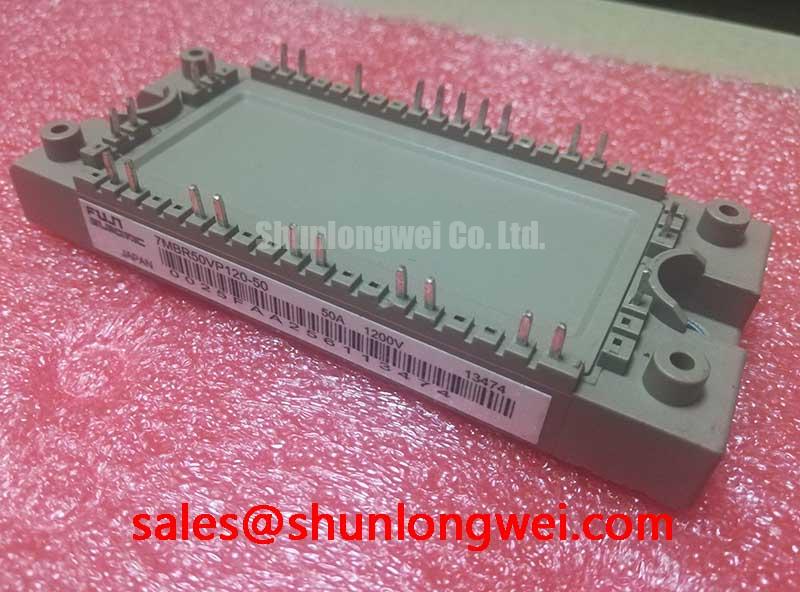
Technical Analysis for System Optimization
The primary value of the 7MBR50VP120-50 lies in its functional integration. By co-packaging the rectifier, brake, and inverter circuits, the module significantly reduces the stray inductance that typically exists between discrete components. This leads to cleaner switching waveforms and potentially lower voltage overshoots, contributing to enhanced system reliability. This consolidation is a key factor for engineers developing compact and cost-effective PIM-based motor drives.
Effective thermal management is enabled by both the module’s construction and its integrated features. The datasheet specifies a thermal resistance from junction to case (Rth(j-c)) of 0.60 °C/W for each inverter IGBT. Think of thermal resistance as the narrowness of a hallway for heat; a lower value represents a wider passage, allowing heat to escape the semiconductor die efficiently. This efficient heat transfer, combined with the built-in NTC thermistor for temperature sensing, allows for robust over-temperature protection and real-time monitoring of the module’s operating condition.
Performance is further defined by the V-Series IGBT technology. The module features a typical collector-emitter saturation voltage (VCE(sat)) of 2.15V at the nominal 50A collector current. This parameter is a direct indicator of conduction losses—the energy dissipated as heat when the IGBT is in its ‘on’ state. A lower VCE(sat) translates to higher inverter efficiency, reducing the thermal load on the heatsink and improving the overall energy economy of the end application.


Optimized Application Scenarios
The characteristics of the 7MBR50VP120-50 make it a strong candidate for several low-to-medium power industrial applications:
- General-Purpose Inverters: Its all-in-one design provides a complete power stage for variable frequency drives (VFDs), simplifying manufacturing and reducing time-to-market.
- AC and DC Servo Drive Amplifiers: The compact package and integrated brake circuit are well-suited for the high power density requirements of precision motion control systems.
- Uninterruptible Power Supplies (UPS): The converter and inverter sections form the core building block for online UPS systems, where reliability and efficiency are essential.
- Small Industrial Motor Control: Ideal for controlling AC motors in applications like conveyor systems, pumps, and fans, where a single, reliable power module is preferred over a discrete solution.
This module is best matched for power conversion systems up to 22kW that require a compact, integrated, and reliable power stage solution.
Key Specifications of the 7MBR50VP120-50
| Parameter | Specification | Notes |
|---|---|---|
| Absolute Maximum Ratings (Tc=25°C) | ||
| Collector-Emitter Voltage (Inverter & Brake) | 1200V | VCES |
| Continuous Collector Current (Inverter) | 50A | IC at Tc=100°C |
| Continuous Collector Current (Brake) | 35A | IC at Tc=80°C |
| Repetitive Peak Reverse Voltage (Converter) | 1600V | VRRM |
| Total Power Dissipation (Inverter) | 280W | Per device |
| Junction Temperature | 175°C (Inverter/Brake), 150°C (Converter) | Tj |
| Electrical Characteristics (Tj=25°C) | ||
| Collector-Emitter Saturation Voltage (Inverter) | 2.15V (typ), 2.70V (max) | VCE(sat) at IC=50A, VGE=15V |
| Forward Voltage (Inverter FWD) | 2.20V (typ), 2.65V (max) | VF at IF=50A |
| Forward Voltage (Converter Diode) | 1.07V (typ), 1.25V (max) | VF at IF=50A |
| Turn-on Time (Inverter) | 0.39 µs (typ) | ton at IC=50A |
| Turn-off Time (Inverter) | 0.54 µs (typ) | toff at IC=50A |
| Thermal and Mechanical Characteristics | ||
| Thermal Resistance (Inverter IGBT) | 0.60 °C/W (max) | Rth(j-c) per arm |
| Isolation Voltage | 2500 Vrms | Viso (AC 1 minute) |
| Mounting Screw Torque | 2.5 – 3.5 N·m | M5 Screw (Recommended) |

Engineer’s FAQ
1. What is the primary benefit of a 7-in-1 module like the 7MBR50VP120-50 for a motor drive design?
The main benefit is system simplification. It integrates the input rectifier, output inverter, and a brake chopper into a single component. This reduces PCB design complexity, lowers component count, minimizes parasitic inductance between stages, and shortens assembly time compared to using discrete components.
2. How should the integrated NTC thermistor be used for thermal protection?
The NTC thermistor provides a means for real-time temperature monitoring. It should be connected to a comparator or microcontroller’s ADC input. Based on the resistance-temperature characteristic curve in the datasheet, the control system can be programmed to trigger alarms or shut down the drive if the module’s internal temperature exceeds safe operating limits, preventing thermal runaway. For more on this, see our guide on the importance of integrated NTCs.
3. What are the recommended gate drive voltage conditions for this module?
The datasheet specifies electrical characteristics with a gate-emitter voltage (VGE) of +15V for turn-on and -15V for turn-off. Using a bipolar supply with a negative turn-off voltage is recommended to ensure the IGBTs remain securely off, especially in high-noise environments, preventing parasitic turn-on events.
4. What is the specified mounting torque, and why is it important?
The recommended mounting screw torque is 2.5 to 3.5 N·m for the M5 screws. Applying the correct torque is critical for ensuring a low-resistance thermal path between the module’s baseplate and the heatsink. Insufficient torque can create air gaps and increase thermal resistance, while excessive torque can damage the module’s substrate.
Enabling Efficient and Reliable Power Conversion
The 7MBR50VP120-50 provides a robust, integrated foundation for developing efficient and compact motor control systems. Its architecture, combining a complete power stage with essential thermal monitoring features in a single module, empowers engineers to accelerate the development cycle while enhancing overall system reliability and power density.