FF1200R17KP4_B2: Technical Analysis of a 1700V, 1200A High-Power IGBT Module
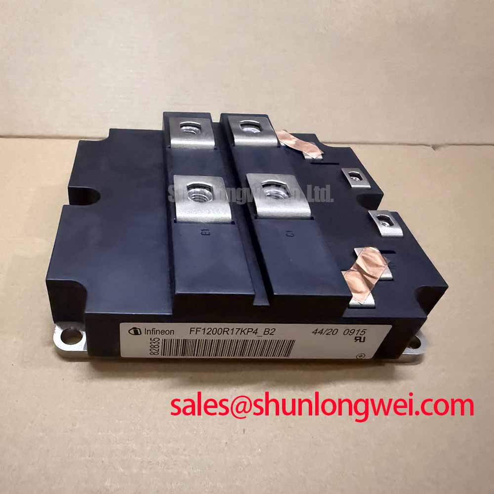
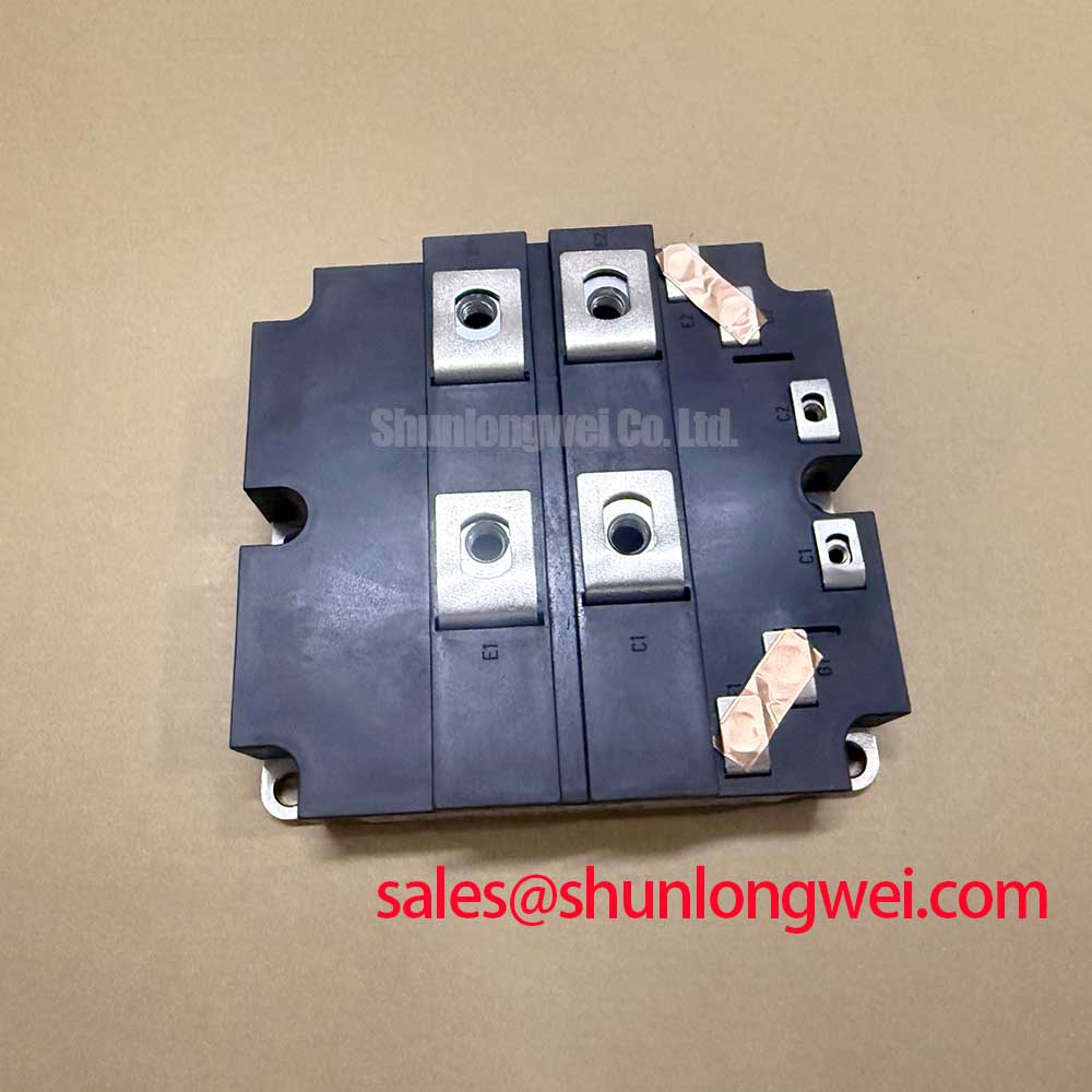
FF1200R17KP4_B2 IGBT Module: 1700V, 1200A High Power Chopper
Introduction to the FF1200R17KP4_B2
The Infineon FF1200R17KP4_B2 is a high-power IGBT module that provides a robust solution for demanding power conversion systems. Its core value proposition is the delivery of high thermal stability and balanced electrical performance, enabled by Infineon’s Trench-Field-Stop IGBT4 and Emitter Controlled 4 diode technology. This combination allows for effective management of both conduction and switching losses, a critical factor in optimizing system efficiency. The module’s low thermal resistance is a key parameter for engineers calculating heatsink requirements, as it facilitates efficient heat dissipation away from the semiconductor junction.
- Core Specifications: 1700 V | 1200 A | Tvj op = 150°C
- Key Advantages: High thermal overhead for robust operation, low overall power losses.
Download the Official Datasheet (PDF)
Technical Analysis for System Design
A defining characteristic of the FF1200R17KP4_B2 is its maximum operating junction temperature (Tvj op) of 150°C. This provides engineers with significant thermal headroom, enhancing the module’s resilience during transient overload conditions and increasing the overall system’s power cycling capability. A higher operating temperature margin allows for more compact thermal management solutions, potentially reducing the size and cost of heatsinks and cooling systems. For more on this topic, see our guide to mastering IGBT thermal design.
The module’s electrical performance is rooted in the Trench-Field-Stop IGBT4 technology. This structure achieves a low collector-emitter saturation voltage (VCE(sat)) of 2.50V at the nominal current and Tvj = 125°C, which directly reduces conduction losses. This is paired with optimized switching characteristics, including low turn-off energy loss (Eoff) of 220 mJ. This balance is critical for applications that operate across a wide range of frequencies and load conditions, as it minimizes total energy loss and improves overall converter efficiency. The concept of thermal resistance from junction to case (RthJC) can be pictured as the width of a pipe for heat removal. The specified value of 0.015 K/W for the IGBT indicates a very wide pipe, ensuring waste heat is evacuated effectively from the silicon to the heatsink.

Optimized Application Scenarios
The specific characteristics of this module make it well-suited for several high-power applications:
- Industrial Motor Drives: The module’s high current handling and thermal robustness are essential for managing the dynamic and often harsh load cycles of large industrial motors.
- Renewable Energy Converters (Solar/Wind): With its 1700V blocking voltage and high efficiency, it is an excellent fit for the central inverters used in megawatt-scale solar farms and wind turbine systems.
- Uninterruptible Power Supplies (UPS): The low conduction and switching losses contribute directly to higher system efficiency, a primary requirement for commercial and industrial UPS.
- Welding Technology: The device’s ability to handle high pulse currents and its robust short-circuit withstand time are advantageous in high-power welding power supplies. An effective gate drive design is crucial in these scenarios.
This module is an optimal match for megawatt-scale power converters requiring high thermal stability and proven operational reliability.
Key Specification Parameters of the FF1200R17KP4_B2
| IGBT – Maximum Rated Values | |
|---|---|
| Collector-Emitter Voltage (VCES) | 1700 V |
| Continuous Collector Current (IC nom) | 1200 A (TC = 100°C) |
| Repetitive Peak Collector Current (ICRM) | 2400 A |
| Gate-Emitter Voltage (VGES) | ±20 V |
| IGBT – Characteristic Values | |
| Collector-Emitter Saturation Voltage (VCE sat) | 2.50 V (typ. at IC=1200A, VGE=15V, Tvj=125°C) |
| Gate Threshold Voltage (VGE(th)) | 5.8 V (typ.) |
| Short Circuit Withstand Time (tPSC) | 10 µs (VGE ≤ 15V, Tvj ≤ 150°C, VCC ≤ 1000V) |
| Diode – Characteristic Values | |
| Forward Voltage (VF) | 2.15 V (typ. at IF=1200A, Tvj=125°C) |
| Reverse Recovery Charge (Qrr) | 350 µC (typ.) |
| Thermal and Mechanical Characteristics | |
| Thermal Resistance, Junction to Case (RthJC) | 0.015 K/W (per IGBT) |
| Isolation Test Voltage (VISOL) | 4.0 kV (RMS, f=50Hz, t=1min) |
Engineer’s Frequently Asked Questions
1. What is the key consideration for the thermal design when using the FF1200R17KP4_B2?
The most critical parameter is the thermal resistance from junction to case (RthJC), specified as 0.015 K/W for the IGBT. This value is fundamental for calculating the total thermal resistance budget. A low RthJC, combined with an appropriate heatsink (defined by RthCH), ensures the junction temperature remains below the 150°C maximum operating limit under expected load conditions.
2. How does the IHM-B package design aid in system assembly?
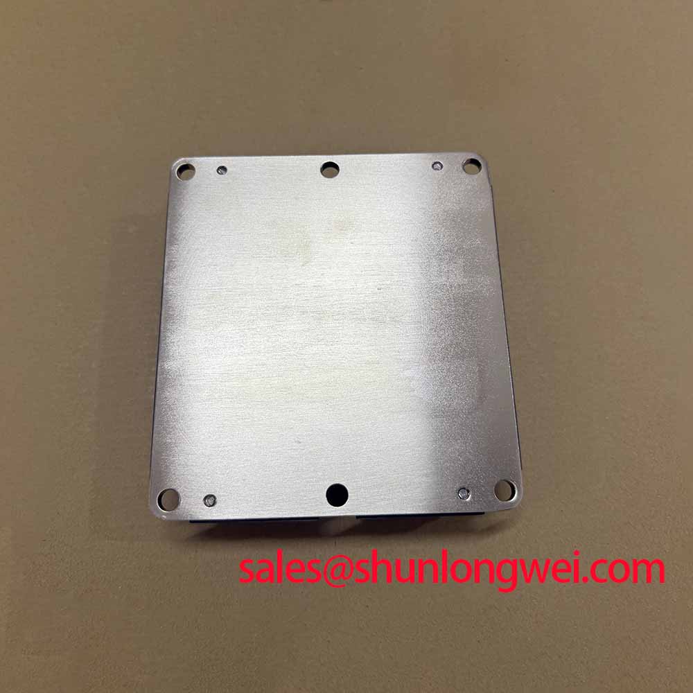
The IHM-B (Insulated High-Power Module B) package is an industry-standard housing. It features a robust mechanical design with screw terminals for high-current connections and an electrically isolated baseplate. This simplifies mounting onto a heatsink and facilitates reliable, low-inductance busbar connections, which is explored further in our article on the impact of parasitic inductance.
3. What does the “soft switching” characteristic of the Emitter Controlled 4 diode imply for the system?
The soft recovery behavior of the integrated freewheeling diode minimizes voltage overshoots and oscillations during turn-off. This reduces electromagnetic interference (EMI) and lessens the stress on the IGBT and surrounding components. It can also simplify or reduce the need for external snubber circuits, saving board space and cost.
4. What is the specified short-circuit withstand time (tPSC) and why is it important?
The FF1200R17KP4_B2 is specified with a short-circuit withstand time of 10 microseconds. This rating defines the duration the IGBT can survive a direct short-circuit event before catastrophic failure. A 10 µs rating provides a sufficient time window for the gate drive protection circuitry to detect the fault and safely shut down the device, which is essential for overall system reliability and safety.
Enabling High-Power System Reliability
The FF1200R17KP4_B2 delivers a well-balanced set of features for high-power system designers. By combining a high operating temperature capability with low conduction and switching losses, it provides the foundation for building efficient, power-dense, and reliable inverters and converters. Its robust thermal and electrical characteristics empower engineers to meet the stringent demands of modern industrial and renewable energy applications.