Infineon FS200R12PE4: A Technical Review for High-Reliability Power Systems
Infineon FS200R12PE4 IGBT Module | 1200V 200A EconoPACK™ 4
Introduction to the FS200R12PE4 Six-Pack IGBT Module
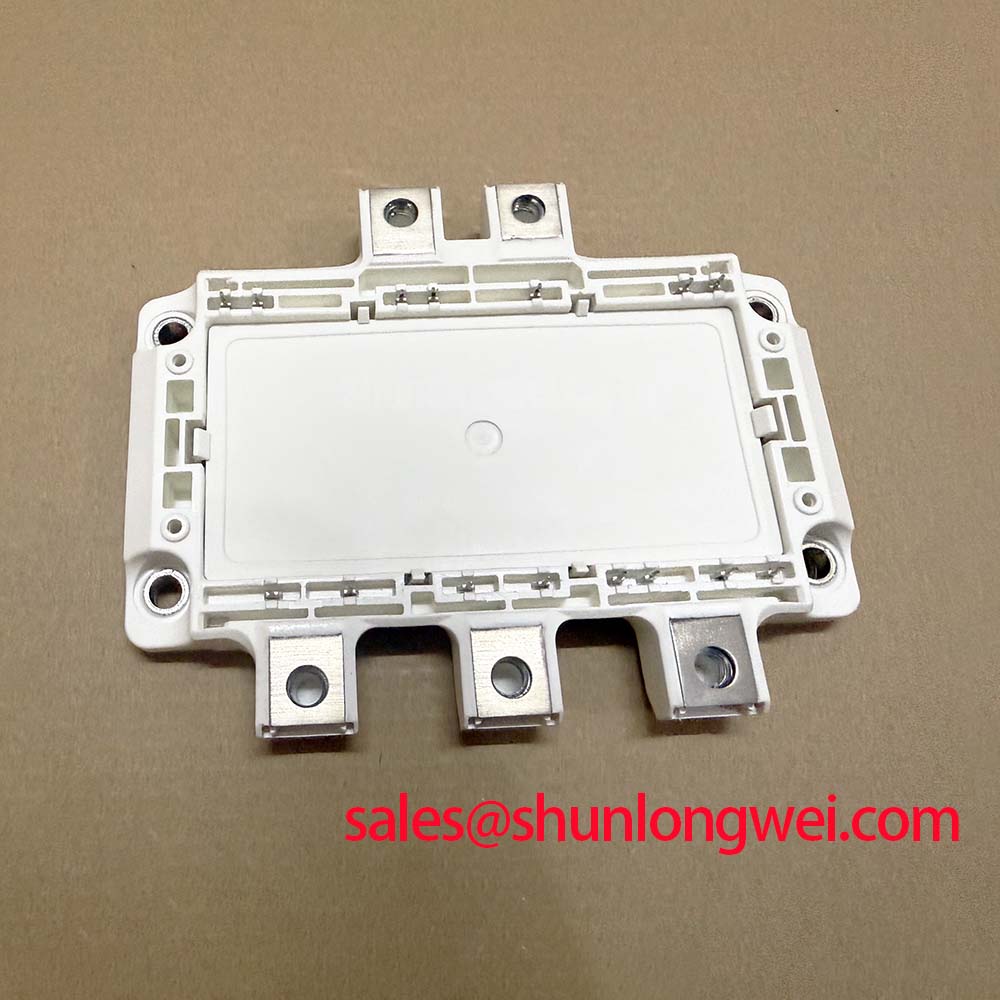
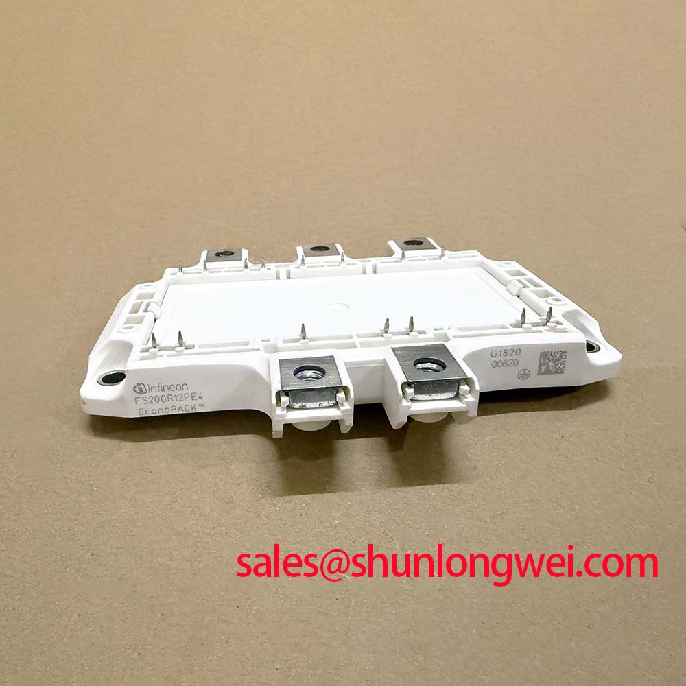
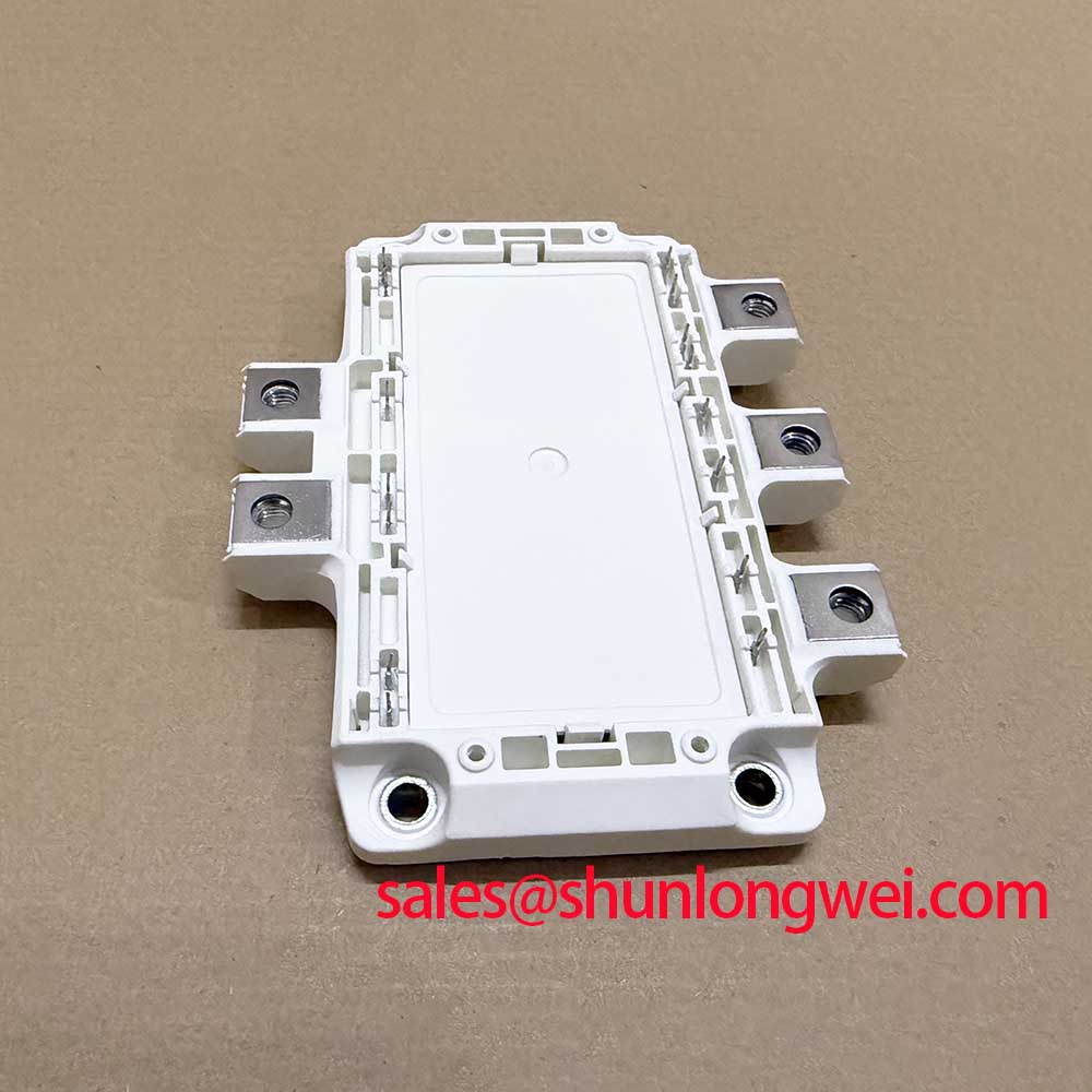
The Infineon FS200R12PE4 is an EconoPACK™ 4 IGBT module providing a robust solution for high-reliability power conversion. It leverages proven TRENCHSTOP™ IGBT4 technology for a balanced performance between conduction and switching losses. This module’s integration of PressFIT contact technology allows for the elimination of solder processes, which simplifies manufacturing and can enhance long-term reliability. It is well-suited for demanding industrial drive applications.
- Core Specifications: 1200V | 200A | VCE(sat) (typ) 1.90V
- Key Advantages: Simplified, solder-free assembly with PressFIT pins, and precise thermal monitoring via an integrated NTC thermistor.
Download the Official FS200R12PE4 Datasheet (PDF)
Technical Analysis for System Design
A defining feature of the FS200R12PE4 is its implementation of PressFIT mounting technology. This solder-free connection method reduces the risk of manufacturing defects like cold solder joints and simplifies the assembly process. By forming a gas-tight, cold-welded connection between the pin and the PCB plated-through hole, PressFIT technology enhances mechanical stability and long-term reliability, a critical factor in industrial systems where vibration and thermal cycling are common stressors.
The module’s electrical performance is founded on Infineon’s TRENCHSTOP™ IGBT4 technology. This chipset provides a favorable trade-off between conduction losses, defined by the collector-emitter saturation voltage (VCE(sat)), and switching losses. The typical VCE(sat) is 1.90 V at a nominal current of 200 A. You can think of VCE(sat) as the electrical “friction” the switch creates when it’s on; a lower value means less energy is wasted as heat. This efficiency directly reduces the demand on the system’s cooling hardware and improves overall energy conversion.
Optimized Application Scenarios
The electrical characteristics and physical construction of the FS200R12PE4 make it a strong candidate for several high-power applications:
- Industrial Motor Drives: Its 200A rating and robust six-pack configuration are ideal for controlling three-phase AC motors in machinery, conveyors, and pump systems.
- Solar Inverters: The 1200V blocking voltage offers the necessary design margin for grid-tied solar applications, ensuring reliable operation under high DC bus voltage conditions.
- Uninterruptible Power Supplies (UPS): The combination of high efficiency from the TRENCHSTOP™ IGBT4 and the reliability of the EconoPACK™ 4 housing is essential for critical backup power infrastructure.
- Commercial and Agricultural Vehicles (CAV): The module’s robust design can withstand the demanding operational environments of electric powertrains in specialty vehicles.
This module is an excellent fit for industrial inverter designs up to 75 kW requiring high operational reliability and a simplified assembly workflow.
Key Electrical and Thermal Specifications
| FS200R12PE4 Module Characteristics (Tvj = 25°C unless otherwise specified) | ||
|---|---|---|
| Parameter | Condition | Value |
| IGBT, Inverter | ||
| Collector-Emitter Voltage (VCES) | – | 1200 V |
| DC Collector Current (IC nom) | – | 200 A |
| Collector-Emitter Saturation Voltage (VCE sat) | IC = 200 A, VGE = 15 V, Tvj = 25°C | 1.90 V (typ) |
| Diode, Inverter | ||
| Forward Voltage (VF) | IF = 200 A, VGE = 0 V, Tvj = 25°C | 1.95 V (typ) |
| Thermal and Mechanical | ||
| Max. Junction Temperature (Tvj op) | – | 150°C |
| Thermal Resistance, Junction to Case (RthJC) | per IGBT | 0.10 K/W (max) |
Engineer’s FAQ for the FS200R12PE4
1. What are the key PCB design rules for using PressFIT pins?
According to the datasheet’s mechanical drawings, the recommended plated-through hole diameter is 1.70 mm with tight tolerances. It is critical to ensure the PCB specifications for copper plating thickness and final hole diameter are met to guarantee a reliable, gas-tight connection during the press-in process. Refer to Infineon’s application notes for detailed guidance.
2. How does the integrated NTC help with system reliability?
The integrated NTC thermistor provides a real-time temperature reading close to the IGBT and diode chips. This allows the system controller to monitor the module’s operating temperature accurately. The controller can then implement thermal protection strategies, such as derating the output power or triggering a shutdown, to prevent the module from exceeding its maximum junction temperature of 150°C.
3. Can the FS200R12PE4 be used in parallel to achieve higher current output?
While paralleling IGBT modules is feasible, it requires careful engineering. The datasheet specifies a positive temperature coefficient for VCE(sat), which is favorable for thermal stability and current sharing between parallel devices. However, achieving balanced current sharing also depends heavily on a symmetrical busbar and gate driver layout to minimize stray inductance mismatches. For guidance on this topic, review resources on high-power IGBT paralleling.
4. What is the maximum repetitive peak collector current?
The datasheet specifies a repetitive peak collector current (ICRM) of 400 A, which is twice the nominal DC collector current. This rating indicates the module’s ability to handle pulsed current loads common in motor control and inverter applications, but it should not be treated as a continuous rating.
Enabling Efficient and Reliable Power Systems
By combining the well-regarded performance of TRENCHSTOP™ IGBT4 technology with the manufacturing and reliability benefits of a PressFIT EconoPACK™ 4 housing, the Infineon FS200R12PE4 provides a solid foundation for engineers developing next-generation power converters. Its balanced electrical characteristics and robust mechanical design support the creation of efficient, durable, and more easily manufactured industrial systems.