Fuji 1MBI600LP-060A IGBT: A Technical Analysis for High-Power Applications
Fuji 1MBI600LP-060A IGBT Module | 600V 600A
High-Current Performance for Industrial Power Conversion
The Fuji Electric 1MBI600LP-060A is a high-current IGBT module engineered for robust performance in demanding power conversion systems. This module provides a potent combination of high power handling and thermal efficiency, built upon a conventional design that facilitates straightforward system integration. It is structured to manage substantial electrical loads while maintaining operational stability, making it a reliable component for high-power industrial equipment.
- Core Specifications: 600V | 600A | VCE(sat) 2.2V (typ)
- Key Advantages: Low conduction losses, robust thermal management.
By delivering a low collector-emitter saturation voltage, the 1MBI600LP-060A directly addresses the need for greater efficiency in applications like high-power inverters, where minimizing heat generation is a primary design objective.
Download Official Datasheet (PDF)
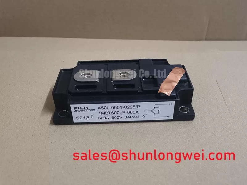
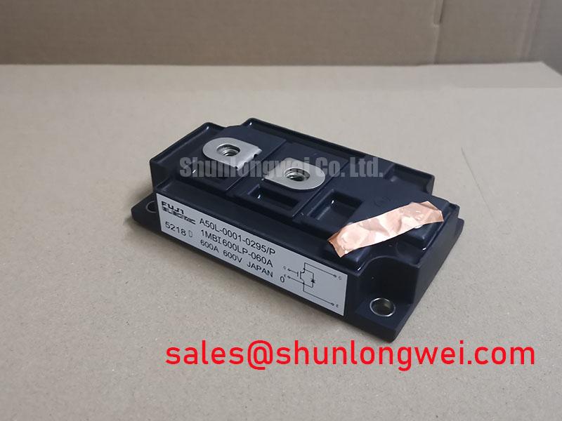
Technical Analysis for System Designers
The engineering value of the 1MBI600LP-060A is rooted in its fundamental electrical and thermal characteristics. Its collector-emitter saturation voltage (VCE(sat)) is specified at a typical value of 2.2V with a 600A collector current at a junction temperature of 125°C. This parameter is critical for calculating conduction losses (P_loss = VCE(sat) × I_C), which are a primary source of heat in a power system. Think of VCE(sat) as the electrical “friction” the current encounters; a lower value means less energy is wasted as heat, leading to improved system efficiency and reduced demands on the cooling system.
Effective thermal management is further supported by the module’s low thermal resistance from junction to case (Rth(j-c)), rated at a maximum of 0.042°C/W for the IGBT. This value represents the efficiency of heat transfer from the silicon die to the module’s baseplate. A lower thermal resistance is analogous to a wider pipe for heat flow; it allows thermal energy to be extracted more effectively, keeping the junction temperature within its safe operating limits (up to 150°C) and contributing to long-term reliability. Understanding these parameters is key to leveraging this module’s full capabilities.
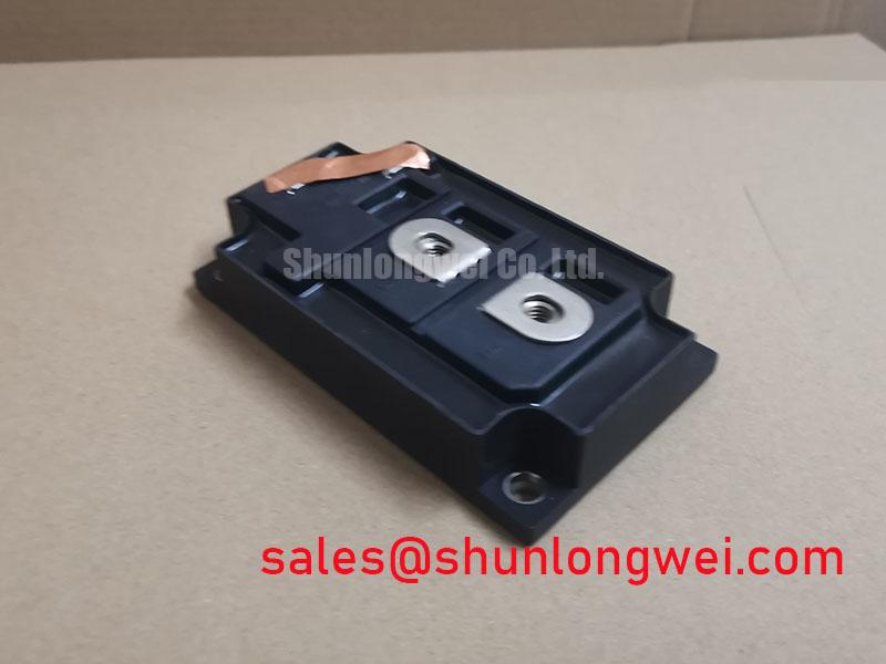
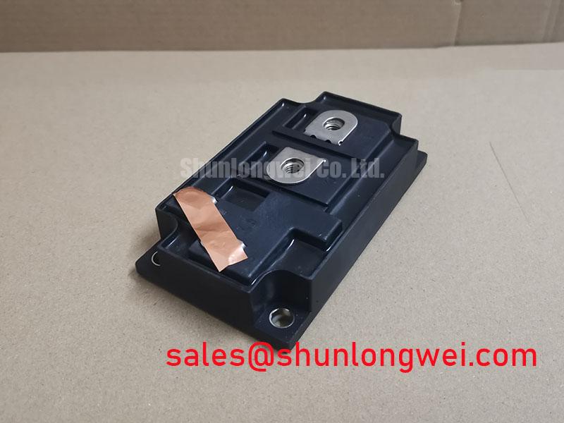
Optimized Application Scenarios
The technical specifications of the 1MBI600LP-060A align it with several high-power industrial applications:
- High-Power Motor Drives (VFDs): The 600A current rating is well-suited for controlling large industrial AC motors where high torque is required.
- Uninterruptible Power Supplies (UPS): Its capacity to handle significant current makes it a reliable choice for the inverter stage in large-scale UPS systems.
- Welding Power Supplies: The module’s robust construction and high current pulse capability are ideal for the demanding electrical environment of industrial welders.
- Renewable Energy Inverters: Suitable for central solar or wind inverters where efficient and reliable DC-to-AC power conversion is necessary.
This module is best matched for high-reliability power systems requiring robust current handling with an emphasis on thermal performance and efficiency.
Key Specifications of the 1MBI600LP-060A
| Absolute Maximum Ratings (at Tc=25°C unless otherwise specified) | |
|---|---|
| Collector-Emitter Voltage (VCES) | 600V |
| Continuous Collector Current (IC) | 600A |
| Repetitive Peak Collector Current (IC puls) | 1200A |
| Gate-Emitter Voltage (VGES) | ±20V |
| Max Power Dissipation (PC) | 2800W |
| Operating Junction Temperature (Tj) | -40 to +150°C |
| Isolation Voltage (Viso) | 2500V (AC, 1 minute) |
| Electrical & Thermal Characteristics | |
| Collector-Emitter Saturation Voltage (VCE(sat)) (Typ. at Tj=125°C) | 2.2V |
| Gate-Emitter Threshold Voltage (VGE(th)) | 5.0V to 8.0V |
| FWD Forward Voltage (VF) (Typ. at Tj=125°C) | 2.0V |
| Thermal Resistance, Junction-to-Case (Rth(j-c)) IGBT | 0.042 °C/W (Max) |
Engineer’s FAQ
1. How are power losses calculated for the 1MBI600LP-060A in an inverter application?
Total power loss is the sum of conduction and switching losses. Conduction loss is calculated using VCE(sat) and the FWD’s forward voltage (VF) from the datasheet curves, multiplied by the on-state current and duty cycle. Switching losses (Eon, Eoff, Err) depend on frequency, DC bus voltage, and gate resistance. For a detailed guide on this process, refer to our article on mastering IGBT thermal design.
2. What are the specified mounting torque values for this module?
The official datasheet specifies a mounting torque of 3.92 ± 0.49 Nm for the M6 mounting screws. The M8 main terminals require a torque of 7.84 ± 0.98 Nm. Applying the correct torque is critical to ensure low thermal resistance to the heatsink and reliable electrical connections without inducing mechanical stress on the module’s substrate.
3. Is an NTC thermistor included for temperature monitoring?
Based on the provided datasheet, the 1MBI600LP-060A does not feature an integrated NTC thermistor. For systems requiring direct module temperature feedback, an external sensor mounted near the module on the heatsink would be necessary. To learn more about the importance of thermal monitoring, read our analysis on the role of the integrated NTC.
4. What are the primary considerations for the gate drive circuit?
A suitable gate drive circuit should provide a gate-emitter voltage (VGE) of +15V for turn-on and a negative voltage (e.g., -5V to -15V) for secure turn-off. The driver must supply sufficient peak current to charge and discharge the IGBT’s input capacitance quickly, minimizing switching times. The gate resistor (Rg) value should be selected to balance switching speed with voltage overshoot and EMI performance.
Enabling High-Power System Design
The 1MBI600LP-060A IGBT module delivers the high-current capability and thermal efficiency necessary for developing reliable and effective industrial power systems. Its straightforward design, combined with documented performance characteristics, provides engineers with a dependable component for managing significant power loads in motor drives, UPS systems, and high-power inverters.