Fuji EVM31-050B: An Integrated Darlington Module for Robust Motor Control
Fuji EVM31-050B: 600V 50A Darlington Power Module
Integrated 3-Phase Inverter for Robust Motor Control
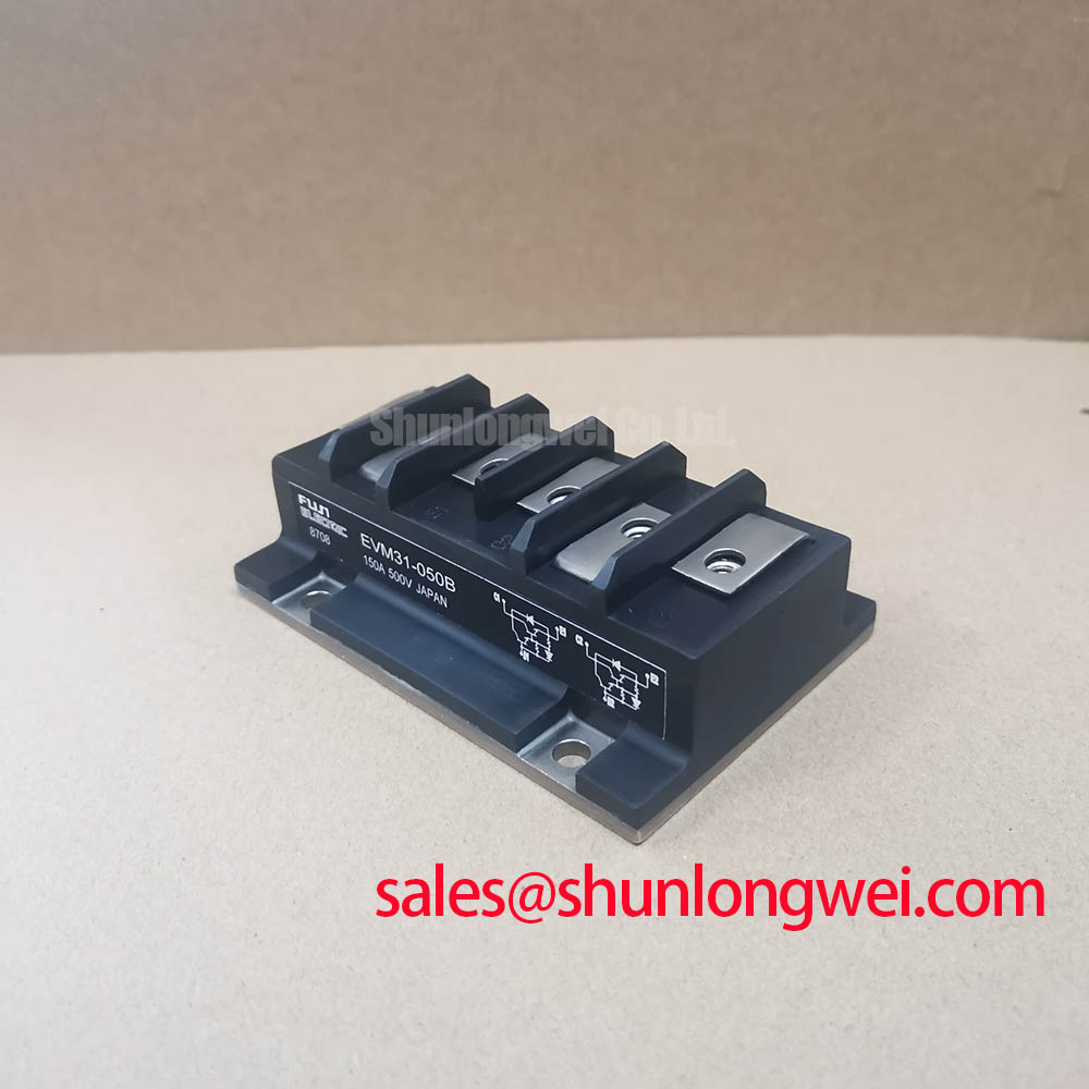
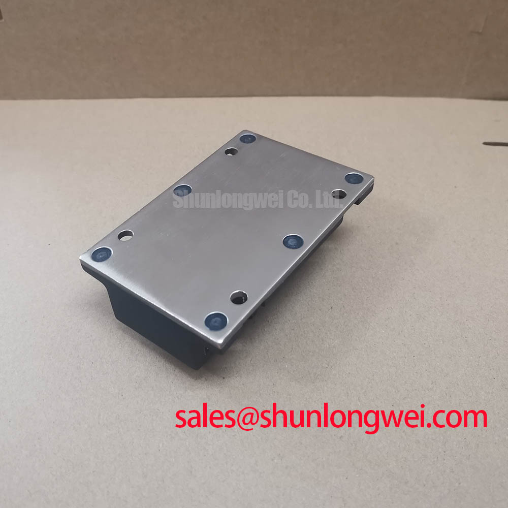
The Fuji Electric EVM31-050B is a Darlington Power Transistor Module that consolidates a full three-phase inverter bridge into a single, electrically isolated package. This integrated design provides a direct solution for simplifying power stage development in motor drives and inverters, leveraging the inherent robustness of Darlington transistor technology for reliable power switching.
- Core Specifications: 600V | 50A | 2500V Isolation
- Key Advantages: Reduces component count and simplifies assembly. Provides a proven, rugged solution for power control.
- Design Consideration: The module’s characteristics offer a straightforward alternative to more complex Intelligent Power Modules (IPMs) where basic, reliable control is the priority.
Download Official Datasheet (PDF)

Technical Analysis of the EVM31-050B Architecture
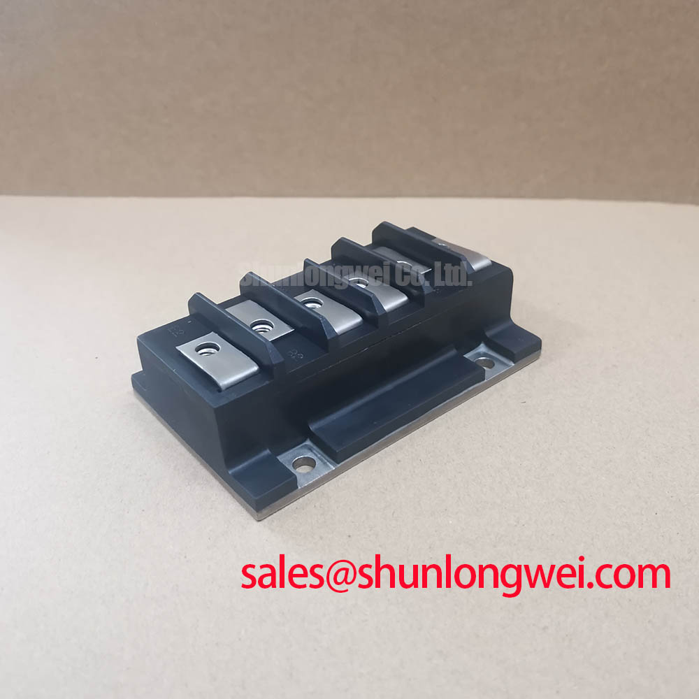
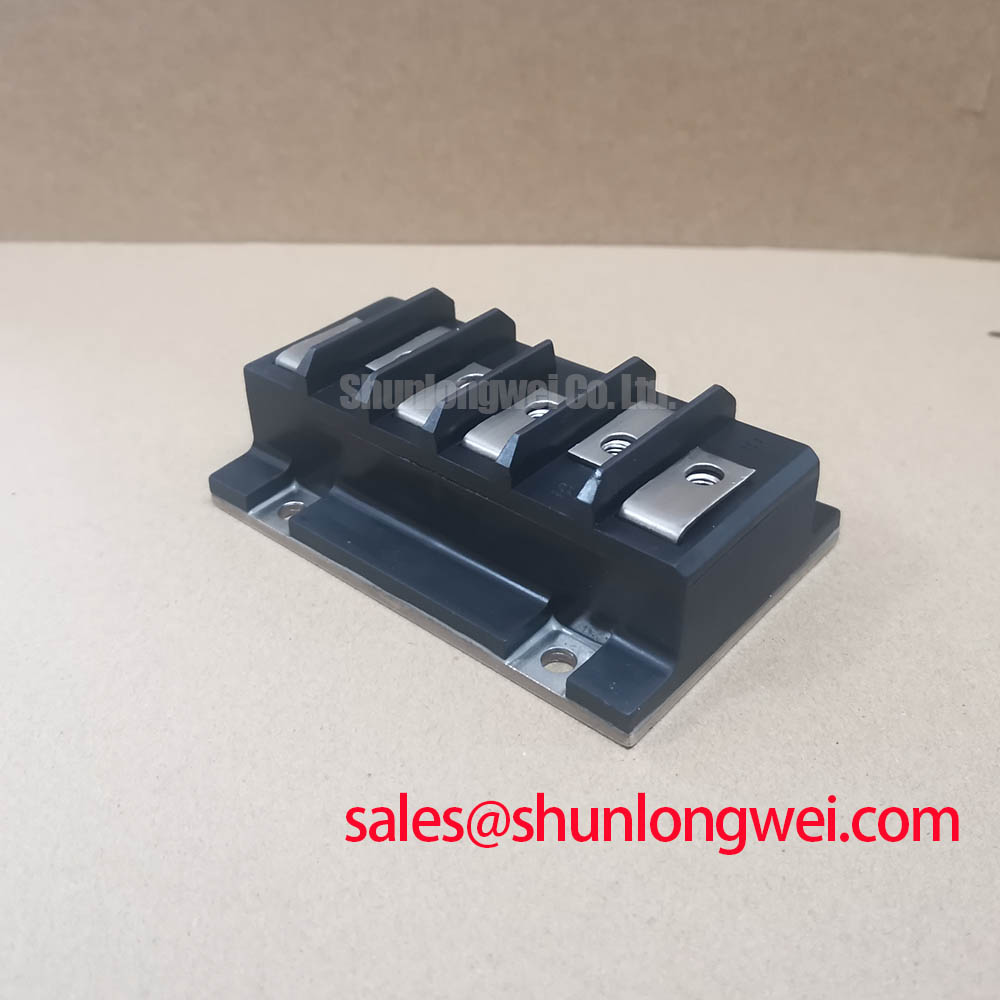
The primary engineering value of the EVM31-050B lies in its “6-in-1” configuration. This module integrates six NPN Darlington transistors with parallel-connected freewheeling diodes, forming a complete power stage for a three-phase Variable Frequency Drive (VFD). By housing all power-switching components in a single housing, designers can significantly reduce PCB layout complexity, minimize stray inductance between components, and streamline the manufacturing assembly process. This level of integration directly contributes to a more compact and potentially more reliable system compared to designs using discrete components.
Effective thermal management is fundamental to power module reliability. The EVM31-050B specifies a maximum collector-emitter saturation voltage (VCE(sat)) of 2.5V at a collector current of 50A. This parameter is the primary source of conduction losses. The module’s thermal resistance from junction to case (Rth(j-c)) is documented at 0.4 °C/W per transistor. This value is critical for heatsink selection. You can visualize thermal resistance as the width of a pipe for heat flow; a lower Rth(j-c) value signifies a wider pipe, allowing heat to escape more effectively from the active semiconductor to the cooling system.
Optimized Application Scenarios
The specific characteristics of the EVM31-050B make it well-suited for several industrial applications.
- AC Motor Drives: The module’s 3-phase bridge topology and 600V/50A ratings are a direct match for controlling small to medium-sized induction motors.
- General Purpose Inverters: Its all-in-one design provides a simplified power stage for basic DC-to-AC power conversion systems.
- Uninterruptible Power Supplies (UPS): The inherent ruggedness of Darlington technology offers high reliability for backup power systems where uptime is critical.
Its integrated design and robust performance make it a strong candidate for cost-sensitive, low-to-medium frequency inverter and motor control systems.
Key Specifications of the EVM31-050B
| Parameter | Value |
|---|---|
| Absolute Maximum Ratings (T_c = 25°C) | |
| Collector-Emitter Voltage (V_CES) | 600 V |
| Collector Current (I_C) | 50 A |
| Collector Power Dissipation (P_C) per Transistor | 180 W |
| Isolation Voltage (V_isol), AC for 1 minute | 2500 V |
| Electrical Characteristics (T_j = 25°C) | |
| DC Current Gain (h_FE) | 75 (Min) |
| Collector-Emitter Saturation Voltage (V_CE(sat)) @ I_C = 50A | 2.5 V (Max) |
| Thermal Characteristics | |
| Thermal Resistance (R_th(j-c)) per Transistor | 0.4 °C/W (Max) |
| Operating Junction Temperature (T_j) | +150 °C |
Engineer’s FAQ
1. What are the primary considerations for selecting a heatsink for the EVM31-050B?
Heatsink selection depends on calculating the total power dissipation and using the module’s thermal resistance. First, determine the total power loss, which is the sum of conduction losses (V_CE(sat) * I_C * Duty Cycle) and switching losses for your specific operating frequency. Then, use the Rth(j-c) value (0.4 °C/W per transistor) to calculate the required thermal resistance of the heatsink to maintain the junction temperature below the 150°C maximum rating.
2. How does the VCE(sat) of this Darlington module compare to a modern IGBT?
The VCE(sat) of 2.5V is characteristic of Darlington technology and is generally higher than that of a modern IGBT module with similar ratings. This results in higher conduction losses. The trade-off is often a simpler gate drive circuit and the established reliability of the Darlington architecture for less demanding, lower-frequency applications.
3. What is the function of the built-in diodes?
The EVM31-050B includes a freewheeling diode (FWD) connected in anti-parallel with each Darlington transistor. When driving an inductive load like a motor, these diodes provide a path for the current to flow when a transistor is switched off, protecting the transistor from potentially damaging voltage spikes.
Enabling Straightforward Power System Design
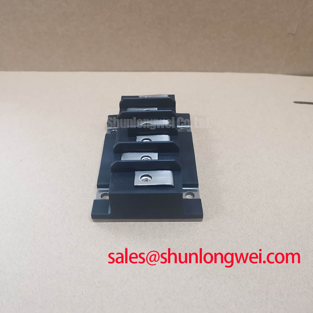
The EVM31-050B power module provides a direct route to implementing robust three-phase power stages. Its high level of integration minimizes external component count and simplifies thermal design, offering a reliable foundation for industrial motor controls and general-purpose inverter systems. This approach allows engineering teams to focus on system-level innovation rather than the complexities of discrete power circuit layout.