NIEC PDMB 200E6: A Technical Analysis of the 600V 200A 6-in-1 IGBT Module
PDMB 200E6 | NIEC 600V 200A 6-in-1 IGBT Module
Introduction and Core Highlights
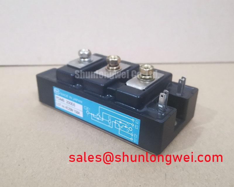
The NIEC PDMB 200E6 is a robust power module that integrates a complete three-phase inverter stage into a single, consolidated package. Its primary engineering value lies in simplifying the design and assembly of high-current motor drives and power converters. By combining six IGBTs and six freewheeling diodes, this module provides a straightforward solution for converting DC power into three-phase AC output, significantly reducing PCB complexity and component count compared to discrete solutions.
- Core Specifications: 600V | 200A | 6-in-1 Inverter Configuration
- Key Advantages: Reduces component count for 3-phase systems, streamlines assembly and thermal management.
This integrated approach is particularly effective for creating reliable industrial power stages where development speed and manufacturing simplicity are critical.
Download the Official PDMB 200E6 Datasheet (PDF)

Technical Analysis: The Value of Integration and Thermal Stability
The core advantage of the PDMB 200E6 module is its 6-in-1 topology. Housing a full three-phase bridge in one component provides significant benefits over using six individual IGBTs. This architecture minimizes the parasitic inductance that occurs in the connections between discrete switches, which can cause voltage overshoots during fast switching events. Furthermore, mounting a single module to a heatsink is far more efficient than managing the thermal interfaces for multiple separate components, ensuring a more uniform temperature distribution across all devices. This design choice is a key consideration in the strategic choice between PIMs and discrete IGBTs.
Effective thermal management is crucial for power module reliability. The PDMB 200E6 specifies a thermal resistance from junction to case (Rth(j-c)) of 0.12 K/W per IGBT. This value can be thought of like the width of a pipe for heat; a lower number means heat can flow more easily from the active silicon chip to the module’s baseplate. With a maximum power dissipation (Pc) of 1040W per IGBT, this efficient thermal path is essential for preventing overheating under heavy loads. It allows engineers to design smaller, more cost-effective cooling systems while maintaining operational stability, a critical factor for mastering thermal design in power systems.
Optimized Application Scenarios
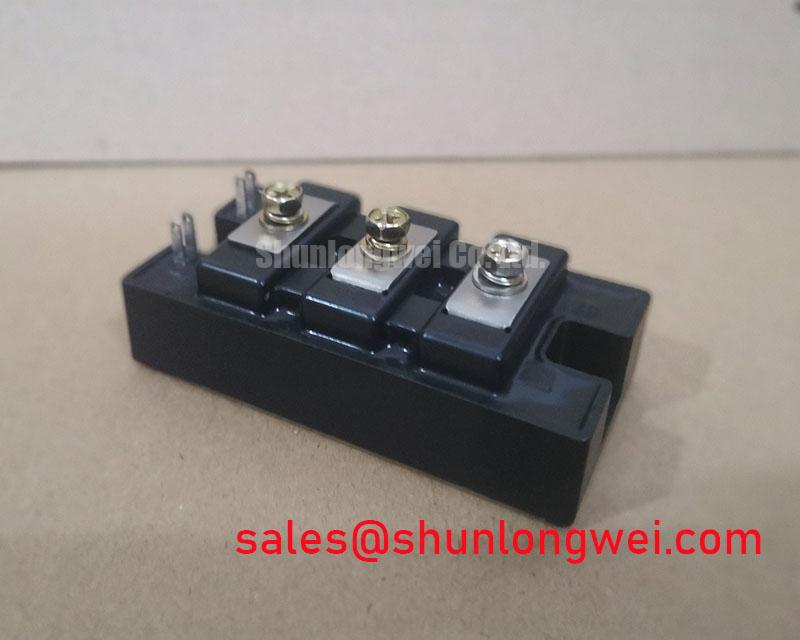
The specific characteristics of the PDMB 200E6 make it a strong candidate for several industrial applications:
- AC Motor Drives: The 6-in-1 configuration is the standard topology for three-phase Variable Frequency Drives (VFDs). Its 200A current rating is sufficient for controlling medium-horsepower induction motors.
- Industrial Power Converters: For general-purpose inverters and power supplies, this module provides a robust and field-proven building block that simplifies the power stage.
- Welding Power Supplies: The high current handling capacity (Ic = 200A) meets the demands of certain welding processes that require sustained, high-amperage DC output.
- Uninterruptible Power Supplies (UPS): The module can serve as the core inverter stage, converting DC battery voltage to stable AC power during a utility outage.
This module is best matched for high-current, three-phase inverter designs where design simplicity, manufacturing speed, and robust thermal performance are primary engineering goals.
Key Specification Parameters
| Absolute Maximum Ratings (Tc = 25°C unless otherwise noted) | |
|---|---|
| Collector-Emitter Voltage (VCES) | 600 V |
| Collector Current (IC) | 200 A |
| Peak Collector Current (ICP) | 400 A (1ms) |
| Max Power Dissipation per IGBT (Pc) | 1040 W |
| Operating Junction Temperature (Tj) | -40 to +150 °C |
| Isolation Voltage (Viso) | 2500 V (AC, 1 minute) |
| Electrical & Thermal Characteristics (Tj = 25°C) | |
| Collector-Emitter Saturation Voltage (VCE(sat)) @ 200A | 2.7 V (Max) |
| Gate-Emitter Threshold Voltage (VGE(th)) | 4 to 8 V |
| Diode Forward Voltage (VF) @ 200A | 2.5 V (Max) |
| Thermal Resistance, Junction-to-Case (Rth(j-c)) – IGBT | 0.12 K/W |
| Thermal Resistance, Junction-to-Case (Rth(j-c)) – Diode | 0.20 K/W |
Engineer’s FAQ
- How do I use the thermal resistance value, Rth(j-c), for heatsink selection?
- Rth(j-c) is a critical parameter for thermal calculations. To estimate the required heatsink performance, you calculate the total temperature rise from the semiconductor junction to the ambient air. The simplified formula is: ΔT = P_diss * (Rth(j-c) + Rth(c-s) + Rth(s-a)), where Rth(c-s) is the thermal resistance of the thermal interface material and Rth(s-a) is the thermal resistance of the heatsink. You must ensure the final junction temperature remains below the 150°C maximum rating.
- What is the recommended mounting torque for the PDMB 200E6?
- The datasheet specifies a mounting torque of 3.9 to 5.9 N·m for the M6 mounting screws. Applying the correct torque is critical. Insufficient torque leads to poor thermal contact and overheating, while excessive torque can warp the baseplate, also compromising thermal performance and potentially damaging the module’s internal structure. For more on this, see our guide on the critical role of terminal torque.
- Is this module suitable for high-frequency applications (e.g., >20 kHz)?
- Based on the typical switching times specified (e.g., turn-off delay of 0.6µs, fall time of 0.4µs), the PDMB 200E6 is optimized for low-to-moderate switching frequencies, typical of industrial motor drives. Operating at high frequencies would likely result in excessive switching losses, requiring significant thermal derating and a very robust cooling system.
- What is the internal circuit configuration?
- The PDMB 200E6 contains six IGBTs and six co-packaged freewheeling diodes arranged in a three-phase bridge topology. This allows it to function as a complete DC-to-AC inverter stage within a single module.
Enabling Robust Power Stage Development
The PDMB 200E6 provides a direct path for engineers to create dependable, high-current power stages. Its integrated 6-in-1 design stands as a practical solution that minimizes assembly complexity and accelerates the development timeline for a wide range of industrial motor control and power conversion systems.