Technical Analysis of the BSM50GD120DN2E3226 IGBT Module
## BSM50GD120DN2E3226 IGBT Module | 1200V 50A Dual
Technical Analysis of the Infineon BSM50GD120DN2E3226 IGBT Module
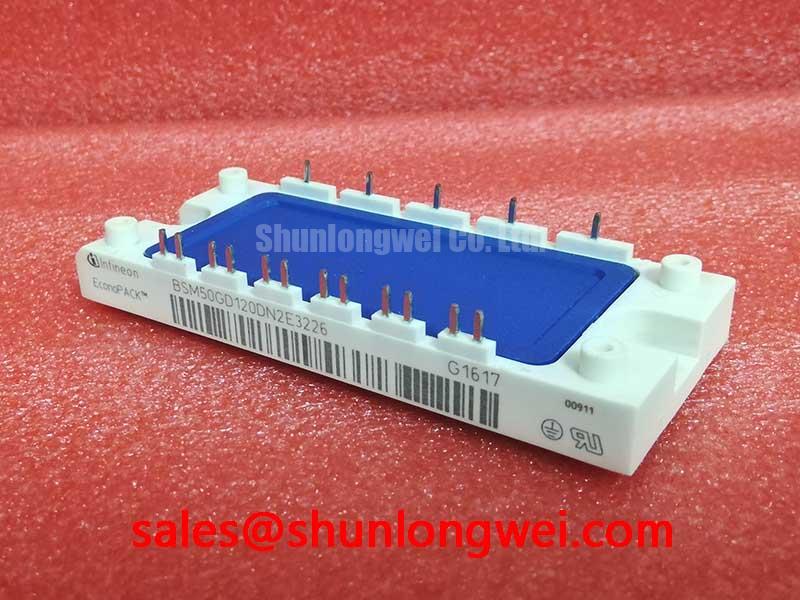
The Infineon BSM50GD120DN2E3226 is a 1200V IGBT power module engineered for efficiency and reliability in power conversion systems. It integrates two IGBTs in a half-bridge configuration within a single EconoPACK™ 2 package, providing a compact solution for motor drives, solar inverters, and uninterruptible power supplies (UPS). A key value of this module is its foundation on TRENCHSTOP™ IGBT3 technology, which balances low conduction losses with robust switching performance for moderate frequency applications.
* **Core Specifications**: 1200V | 50A | VCE(sat) (typ) 2.5V
* **Key Advantages**: Low conduction losses, integrated NTC for temperature monitoring.
* **Design Consideration**: The module’s low thermal resistance from junction to case (RthJC) facilitates effective heatsink design and thermal management.
Download the Official BSM50GD120DN2E3226 Datasheet (PDF)

A Deeper Look at Technical Performance
The engineering value of the BSM50GD120DN2E3226 is rooted in its datasheet specifications. The collector-emitter saturation voltage (VCE(sat)) is a critical parameter, specified as typically 2.5V at the nominal current of 50A and a junction temperature of 125°C. This figure directly impacts conduction losses; a lower VCE(sat) results in less power dissipated as heat during the on-state, which enhances overall system efficiency. This is particularly beneficial in applications like motor drives that experience sustained current flow.
Effective thermal management is fundamental to the reliability of any power module. The BSM50GD120DN2E3226 specifies a maximum thermal resistance from junction to case (RthJC) of 0.35 K/W for the IGBT. This value can be viewed as the thermal bottleneck of the component. To use an analogy, thermal resistance is like the narrowness of a pipe carrying heat away from the chip. A lower value, like the one found in this module, signifies a wider “pipe,” allowing heat to be extracted more efficiently to the heatsink. This robust thermal performance helps maintain the junction temperature within safe operating limits, crucial for achieving a long operational lifetime.

Optimized Application Scenarios
The specific characteristics of the BSM50GD120DN2E3226 make it a strong candidate for several demanding applications:
- AC Motor Drives: In variable frequency drives (VFDs), its low VCE(sat) reduces heat dissipation, enabling more compact drive designs or higher power output from a given footprint.
- Uninterruptible Power Supplies (UPS): The module’s robust construction and half-bridge configuration are well-suited for the inverter stage of UPS systems, where reliability is paramount.
- Solar Inverters: For string inverters, efficiency is key to maximizing energy yield. The low conduction losses of this module contribute directly to higher overall conversion efficiency.
- Welding Equipment: The module’s ability to handle pulsed collector currents up to 100A (at TC = 80°C) provides the necessary robustness for welding power supplies.
This module’s balance of low on-state voltage and robust thermal characteristics makes it an optimal choice for moderate-frequency, hard-switching power conversion topologies.
Key Specifications of the BSM50GD120DN2E3226
| Parameter | Value | |
|---|---|---|
| Absolute Maximum Ratings (TC = 25°C unless otherwise specified) | ||
| Collector-Emitter Voltage (VCES) | 1200 V | |
| DC Collector Current (IC) @ TC = 80°C | 50 A | |
| Pulsed Collector Current (ICpuls) @ TC = 80°C, tp = 1 ms | 100 A | |
| Gate-Emitter Voltage (VGES) | ±20 V | |
| Total Power Dissipation per IGBT (Ptot) | 350 W | |
| Electrical & Thermal Characteristics (Tj = 25°C unless otherwise specified) | ||
| Collector-Emitter Saturation Voltage (VCE(sat)) | @ IC = 50A, VGE = 15V, Tj = 25°C | 3.1 V (max) |
| @ IC = 50A, VGE = 15V, Tj = 125°C | 2.5 V (typ), 3.7 V (max) | |
| Gate Threshold Voltage (VGE(th)) | 4.5V (min) to 6.5V (max) | |
| Thermal Resistance, Junction-to-Case (RthJC), per IGBT | ≤ 0.35 K/W | |
| Thermal Resistance, Junction-to-Case (RthJCD), per Diode | ≤ 0.7 K/W | |
Note: This table presents a selection of key parameters. For complete details, refer to the official datasheet.
Engineer’s FAQ
1. How does the thermal resistance of the BSM50GD120DN2E3226 impact heatsink selection?
The low RthJC of 0.35 K/W per IGBT ensures efficient heat transfer from the silicon die to the module’s baseplate. This allows engineers to use a smaller, more cost-effective heatsink for a given power dissipation or to operate at higher power levels with a given heatsink, simplifying the overall thermal design of the system.
2. What are the recommended mounting torque specifications for this EconoPACK™ 2 module?
While the datasheet provides mechanical outlines, it does not specify a mounting torque. However, for modules of this type, it is critical to apply the correct and uniform torque to the mounting screws to ensure a low-resistance thermal path to the heatsink. Insufficient torque leads to poor contact, while excessive torque can damage the module. Always consult the manufacturer’s general application notes for the EconoPACK™ housing for precise torque values and mounting procedures.
3. What is the benefit of the integrated NTC thermistor?
The integrated NTC (Negative Temperature Coefficient) thermistor provides a direct, real-time measurement of the module’s baseplate temperature. This allows the system’s controller to implement crucial protection features, such as reducing the output current (derating) if the temperature exceeds a safe limit or triggering a system shutdown in a critical over-temperature event. This is a vital feature for building reliable and fault-tolerant power systems.
4. Does the positive temperature coefficient of VCE(sat) aid in paralleling?
Yes. The datasheet shows that as the junction temperature (Tj) increases, the VCE(sat) also increases. This positive temperature coefficient is beneficial for paralleling multiple modules. If one module starts to carry more current and heats up, its on-state voltage drop will increase, naturally forcing current to redirect to the cooler, parallel modules. This self-balancing effect helps prevent thermal runaway and ensures stable current sharing among the devices.
Enabling Efficient Power Conversion
The Infineon BSM50GD120DN2E3226 provides a robust and field-proven solution for power electronics designers. By leveraging TRENCHSTOP™ IGBT3 technology, it delivers low conduction losses that directly contribute to higher system efficiency. Its integration into the industry-standard EconoPACK™ 2 housing, complete with an NTC thermistor, simplifies thermal management and enhances system-level reliability, empowering engineers to develop compact and durable power conversion systems.