Technical Analysis of the Powerex CM200DY-12H IGBT Module
“`html
Powerex CM200DY-12H Dual IGBT Module | 600V 200A
Introduction to the CM200DY-12H IGBT Module
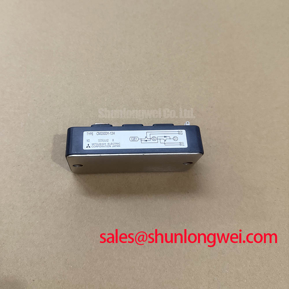
The Powerex CM200DY-12H is an H-Series dual IGBT module engineered to provide a balanced performance profile for medium-frequency power conversion systems. It integrates two IGBTs in a half-bridge configuration, offering a robust solution that balances conduction and switching losses. This design approach enables reliable operation in demanding industrial applications where efficiency and thermal stability are primary objectives.
- Core Specifications: 600V | 200A | VCE(sat) 2.7V max
- Key Advantages: Facilitates predictable thermal management, suited for hard-switching topologies.
- Design Consideration: The module’s low thermal impedance from junction to case is a critical parameter for effective heatsink design, ensuring heat is efficiently dissipated from the semiconductor die.
For complete electrical and thermal specifications, refer to the official documentation: Download the Official CM200DY-12H Datasheet (PDF).

Technical Analysis of Core Features
A detailed review of the datasheet reveals the engineering trade-offs that define the CM200DY-12H’s performance. The maximum collector-emitter saturation voltage (VCE(sat)) is specified at 2.7V at a junction temperature of 125°C. This parameter is directly proportional to conduction losses, a primary source of heat generation in the device. Understanding this value allows engineers to accurately calculate the power dissipated during the on-state, which is essential for managing the overall thermal budget of the power system. For more information on this topic, explore this guide to VCE(sat).
Effective thermal dissipation is critical for reliability. The CM200DY-12H features a thermal resistance from junction to case (Rth(j-c)) of 0.16°C/W per IGBT. You can think of thermal resistance as the narrowness of a pipe; a lower value indicates a wider pipe that allows heat to flow more easily. This low thermal resistance ensures an efficient thermal path from the silicon chip to the module’s baseplate, simplifying heatsink selection and helping to prevent the device from exceeding its maximum junction temperature of 150°C. Proper IGBT thermal design is fundamental to system longevity.
The module’s switching characteristics, including turn-on energy (Eon) of 20 mJ and turn-off energy (Eoff) of 14 mJ, are crucial for applications operating at higher frequencies. These values define the energy lost during each switching transition. As frequency increases, these switching losses can become a significant portion of the total power loss. The datasheet provides these figures under specific test conditions, enabling engineers to model system efficiency and verify that the thermal management system can handle the load. A deep understanding of the free-wheeling diode is also key to optimizing performance.
Optimized Application Scenarios
The CM200DY-12H module’s specifications make it well-suited for several industrial power conversion applications:
- AC Motor Drives: Its 200A current capability and half-bridge configuration are ideal for constructing inverter legs in variable frequency drives (VFDs).
- Uninterruptible Power Supplies (UPS): The module’s robust electrical characteristics and proven reliability support the high-availability requirements of inverter and converter stages in UPS systems.
- Welding Power Supplies: It can effectively manage the high-current, pulsed-power demands characteristic of modern welding equipment.
- High-Power Switched-Mode Power Supplies (SMPS): The defined switching energies and thermal performance support its use in DC-DC converters for industrial power systems.
Its balanced electrical and thermal specifications make it a strong candidate for industrial systems requiring reliable power control in the 20 to 50 kW range.

Key Specifications of the CM200DY-12H
| Absolute Maximum Ratings (Tj = 25°C) | |
|---|---|
| Collector-Emitter Voltage (VCES) | 600 Volts |
| Gate-Emitter Voltage (VGES) | ±20 Volts |
| Collector Current (IC) | 200 Amperes |
| Peak Collector Current (ICM) | 400 Amperes |
| Maximum Power Dissipation (PC) | 780 Watts |
| Electrical Characteristics (Tj = 25°C unless otherwise specified) | |
| Max Collector-Emitter Saturation Voltage (VCE(sat)) | 2.7 Volts (at IC = 200A, VGE = 15V, Tj = 125°C) |
| Collector Cut-off Current (ICES) | 1 mA (at VCE = VCES) |
| Gate-Emitter Threshold Voltage (VGE(th)) | 4.5 – 8.5 Volts |
| Thermal and Mechanical Characteristics | |
| Thermal Resistance, Junction to Case (Rth(j-c)) per IGBT | 0.16 °C/W |
| Isolation Voltage (Viso) | 2500 Vrms |
Engineer’s FAQ for the CM200DY-12H
1. How do I calculate the junction temperature for my heatsink design?
To a first approximation, you can calculate the junction temperature (Tj) using the formula: Tj = Tc + (Rth(j-c) * P_loss), where Tc is the case temperature, Rth(j-c) is the junction-to-case thermal resistance (0.16 °C/W), and P_loss is the total power dissipation (conduction + switching losses). For accurate results, always consult the thermal impedance curves in the datasheet.
2. What is the recommended gate drive voltage for this module?
The datasheet specifies electrical characteristics with a gate-emitter voltage (VGE) of +15V for turn-on. The absolute maximum VGES is ±20V. A common practice for driving this type of module is to use a split-rail supply, such as +15V for turn-on and a negative voltage (e.g., -5V to -10V) for turn-off to ensure noise immunity.
3. What is the role of the integrated free-wheeling diode (FWD)?
The FWD is co-packaged with the IGBT and provides a path for inductive load current to flow when the IGBT is turned off. This is essential in motor drive and inverter circuits to prevent large voltage spikes across the IGBT, which could damage the device. The CM200DY-12H includes an FWD with a maximum forward voltage (VEC) of 2.7V.
Enabling Reliable Power System Design
The Powerex CM200DY-12H provides a well-documented and robust platform for power electronics engineers. By offering a solid combination of current handling, moderate switching speed, and effective thermal characteristics in a standard isolated package, it empowers the design of efficient and dependable power conversion systems for a range of industrial applications. For further reading on related topics, see our guides on power semiconductors.
“`