“`json { “@context”: “https://schema.org”, “@graph”: [ { “@type”: “Product”, “name”: “Fuji 7MBR100U2B060-50 | 600V 100A 7-in-1 IGBT Module”, “mpn”: “7MBR100U2B060-50”, “sku”: “7MBR100U2B060-50”, “description”: “The Fuji Electric 7MBR100U2B060-50 is a highly integrated 7-in-1 IGBT module from the U-Series. It consolidates a full three-phase inverter, brake chopper, and three-phase rectifier into a single, compact package, engineered to reduce system complexity and component count in space-constrained power conversion applications like motor drives.”, “brand”: { “@type”: “Brand”, “name”: “Fuji Electric” }, “category”: “Power Semiconductor Module”, “image”: [ “https://www.slw-ele.com/wp-content/uploads/2021/10/20211026_61786d5da190d.jpg”, “https://www.slw-ele.com/wp-content/uploads/2021/10/20211026_61786d5dcded1.jpg”, “https://www.slw-ele.com/wp-content/uploads/2021/10/20211026_61786d5de3076.jpg” ], “additionalProperty”: [ { “@type”: “PropertyValue”, “name”: “Collector-Emitter Voltage (Vces)”, “value”: “600V” }, { “@type”: “PropertyValue”, “name”: “Continuous Collector Current (Ic)”, “value”: “100A”, “description”: “at Tc=100°C” }, { “@type”: “PropertyValue”, “name”: “Collector-Emitter Saturation Voltage (VCE(sat))”, “value”: “1.7V”, “description”: “Typical value at Ic=100A, Tj=125°C” }, { “@type”: “PropertyValue”, “name”: “Thermal Resistance (Rth(j-c)) – Inverter IGBT”, “value”: “0.28 °C/W” }, { “@type”: “PropertyValue”, “name”: “NTC Resistance (R25)”, “value”: “5.0 kΩ”, “description”: “at 25°C” } ], “subjectOf”: { “@type”: “WebPage”, “name”: “Official Datasheet (PDF)”, “url”: “https://www.fujielectric.com/products/semiconductor/model/igbt/datasheet/6_2/7MBR100U2B060-50.pdf”, “encodingFormat”: “application/pdf” } }, { “@type”: “FAQPage”, “mainEntity”: [ { “@type”: “Question”, “name”: “What are the primary benefits of using an integrated 7-in-1 module like the 7MBR100U2B060-50 over discrete components?”, “acceptedAnswer”: { “@type”: “Answer”, “text”: “Using this module reduces design complexity, manufacturing time, and PCB size by integrating the rectifier, brake, and inverter circuits. This consolidation also minimizes stray inductance and can improve overall system reliability compared to a design with numerous discrete parts.” } }, { “@type”: “Question”, “name”: “How is the integrated NTC thermistor used for over-temperature protection?”, “acceptedAnswer”: { “@type”: “Answer”, “text”: “The built-in NTC thermistor provides real-time temperature feedback from inside the module. Its resistance decreases predictably as temperature increases. A control circuit, like a microcontroller, monitors this resistance. If it corresponds to a pre-set maximum temperature, the controller can trigger a fault, reduce power, or shut down the system to prevent thermal damage.” } }, { “@type”: “Question”, “name”: “What is the maximum recommended case temperature (Tc) for continuous operation at 100A?”, “acceptedAnswer”: { “@type”: “Answer”, “text”: “Based on the Safe Operating Area (SOA) chart in the official datasheet, the maximum allowable case temperature for continuous DC operation at 100A is 100°C. Exceeding this can cause the junction temperature (Tj) to surpass its 150°C maximum limit, risking damage and reducing reliability.” } } ] } ] } “`
“`html
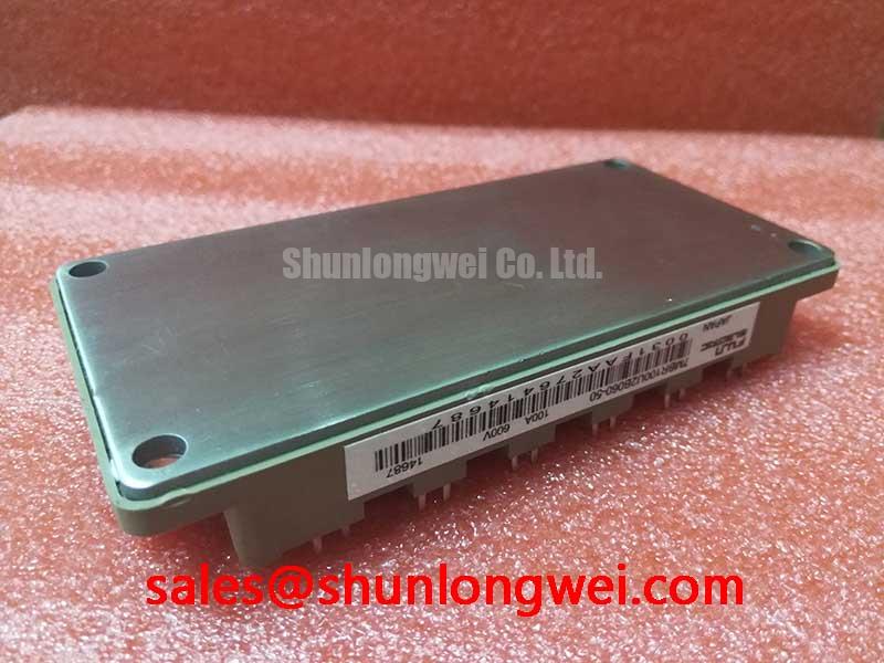
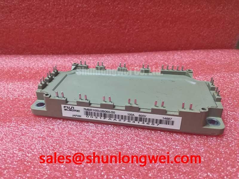
Fuji 7MBR100U2B060-50 | 600V 100A 7-in-1 IGBT Module
Integrated Power Stage for Compact Motor Drives
The Fuji Electric 7MBR100U2B060-50 is a highly integrated 7-in-1 IGBT module from the U-Series. It consolidates a full three-phase inverter, brake chopper, and three-phase rectifier into a single, compact package. This architecture is engineered to reduce system complexity and component count in space-constrained power conversion applications. By integrating these multiple stages, the module provides a streamlined foundation for efficient motor drive designs.
- Core Specifications: 600V | 100A | VCE(sat) 1.7V (typ)
- Key Advantages: Reduces overall component count and PCB footprint, simplifies thermal management, and enhances system reliability with an integrated NTC thermistor.
Download Official Datasheet (PDF)
Technical Analysis of the 7MBR100U2B060-50
A primary engineering advantage of the 7MBR100U2B060-50 is its high level of integration. The 7-in-1 configuration includes a three-phase diode bridge for AC-DC rectification, a brake chopper IGBT with its own freewheeling diode (FWD) for managing regenerative energy, and a full three-phase IGBT inverter bridge for motor control. This consolidation directly addresses the challenge of designing compact systems. Compared to solutions using discrete components, this module significantly reduces the required PCB area, minimizes parasitic inductance between stages, and simplifies the manufacturing assembly process. This approach is fundamental to achieving high power density in modern Variable Frequency Drive (VFD) systems.

Efficiency and Thermal Performance
System efficiency is directly influenced by conduction and switching losses. The inverter IGBTs in this module exhibit a typical collector-emitter saturation voltage (VCE(sat)) of 1.7V at the nominal 100A current (Tj=125°C). The accompanying FWDs feature a low forward voltage (Vf) of 1.55V. These low voltage drops minimize power dissipated as heat during operation. This efficiency is complemented by effective thermal performance. The thermal resistance from junction to case (Rth(j-c)) for a single inverter IGBT is specified at 0.28 °C/W. This value can be imagined like the width of a pipe for heat flow; a lower number signifies a wider pipe, allowing heat to be evacuated from the semiconductor die to the heatsink more effectively. This facilitates a more reliable thermal design and can reduce the size of the required cooling system.
Optimized Application Scenarios
The specific characteristics of the 7MBR100U2B060-50 make it a strong candidate for several industrial applications:
- Compact Variable Frequency Drives (VFDs): The all-in-one design is ideal for small motor drives where PCB space and ease of assembly are critical.
- Servo Drives: Low conduction losses contribute to the high-efficiency operation required for precise motion control systems.
- General Purpose Inverters: Its 600V/100A rating provides a robust power stage for a variety of industrial inverter applications.
- Uninterruptible Power Supplies (UPS): The integrated rectifier and inverter stages simplify the design of online UPS systems, improving power density.
This module is an optimal match for motor control systems requiring a complete, thermally efficient power stage in a single, compact component.
Key Technical Specifications
| Parameter | Value |
|---|---|
| Absolute Maximum Ratings (Tc=25°C) | |
| Collector-Emitter Voltage (Vces) | 600V |
| Continuous Collector Current (Ic) | 100A (Tc=100°C) |
| Collector Power Dissipation (Pc) – Per IGBT | 390W |
| Operating Junction Temperature (Tj) | +150°C |
| Inverter Part Electrical Characteristics (Tj=125°C) | |
| Collector-Emitter Saturation Voltage (VCE(sat)) | 1.7V (typ) / 2.2V (max) @ Ic=100A |
| FWD Forward Voltage (Vf) | 1.55V (typ) / 2.0V (max) @ If=100A |
| NTC Thermistor Characteristics | |
| Resistance at 25°C (R25) | 5.0 kΩ ± 5% |
| B-Constant (B(25/50)) | 3375 K ± 2% |
| Thermal Characteristics | |
| Thermal Resistance (Rth(j-c)) – Inverter IGBT | 0.28 °C/W (per chip) |
| Thermal Resistance (Rth(j-c)) – Inverter FWD | 0.45 °C/W (per chip) |
Engineer’s Frequently Asked Questions
1. What are the primary benefits of using an integrated 7-in-1 module like the 7MBR100U2B060-50 over discrete components?
Using this module reduces design complexity, manufacturing time, and PCB size by integrating the rectifier, brake, and inverter circuits. This consolidation also minimizes stray inductance and can improve overall system reliability compared to a design with numerous discrete parts. For a detailed comparison, explore this analysis of PIM vs. discrete IGBTs.
2. How is the integrated NTC thermistor used for over-temperature protection?
The built-in NTC thermistor provides real-time temperature feedback from inside the module. Its resistance decreases predictably as temperature increases, according to the R-T characteristics in the datasheet. A control circuit, typically a microcontroller, can monitor this resistance value. If it drops to a level corresponding to a pre-set maximum temperature limit, the controller can trigger a fault, reduce the PWM output, or shut down the system to prevent thermal damage. The use of an integrated NTC thermistor is crucial for robust protection schemes.
3. What is the maximum recommended case temperature (Tc) for continuous operation at 100A?
Based on the Safe Operating Area (SOA) chart (Fig. 4) in the official datasheet, the maximum allowable case temperature for continuous DC operation at 100A is 100°C. Exceeding this value can lead to the junction temperature (Tj) surpassing its 150°C maximum limit, which can degrade the module’s lifespan and reliability.
This power semiconductor module provides a functionally dense and thermally efficient solution for engineers developing the next generation of industrial motor controls and power converters. Its integrated nature allows for a direct path to smaller, more reliable system designs without compromising on electrical performance.
“`