Based on the technical analysis provided, I have a question regarding the practical trade-offs for this module in a design. The article highlights the 1700V rating as a key advantage for robustness in applications like industrial motor drives. However, the maximum VCE(sat) is listed as 3.6V at 100A, which seems relatively high and would lead to significant conduction losses (Pcond = VCE(sat) * IC ≈ 360W per switch). How should an engineer balance the benefit of the high voltage safety margin against the potential for lower efficiency due to these conduction losses? Are there specific operating conditions or switching frequencies where this NPT-IGBT module would be most effective despite the higher VCE(sat)?
BSM100GB170DLC: 1700V, 100A Half-Bridge NPT-IGBT Module
Technical Analysis of the BSM100GB170DLC Power Module
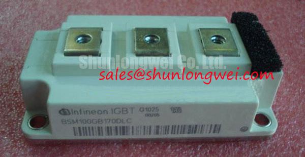
The BSM100GB170DLC is a half-bridge IGBT module from EUPEC (an Infineon Technologies company) that provides a robust solution for high-voltage power conversion. Its primary value stems from a high collector-emitter blocking voltage of 1700V and an integrated NTC thermistor for direct thermal feedback. This combination enables the development of reliable systems with substantial voltage safety margins and precise temperature management.
- Core Specifications: 1700V | 100A | VCE(sat) 3.6V (max)
- Key Engineering Advantages: Provides high blocking voltage for increased system robustness and incorporates an NTC for simplified, effective thermal monitoring and protection.
These features deliver the necessary performance for demanding industrial power control applications. For detailed electrical and thermal characteristics, consult the official component documentation.
Download the BSM100GB170DLC Datasheet (PDF)
In-Depth Technical Characteristics
A standout parameter of the BSM100GB170DLC is its 1700V collector-emitter voltage (VCES) rating. This high voltage capability offers a significant design advantage over standard 1200V modules. It allows for operation with higher DC bus voltages and provides a greater safety margin against transient overvoltages common in industrial environments. This is particularly valuable in systems where reliability under fluctuating line conditions is critical, directly contributing to a more resilient final product.
Effective thermal management is fundamental to the reliability of any power semiconductor system. The module’s specified junction-to-case thermal resistance (Rth(j-c)) is 0.17 K/W for each IGBT and 0.36 K/W for each diode. This parameter can be visualized as the width of a pipe for heat flow; a lower value indicates a wider pipe, allowing heat to dissipate more efficiently from the semiconductor die to the heatsink. This low thermal resistance, combined with the integrated NTC, gives engineers precise control over the module’s operating temperature.
Optimized Application Scenarios
The specifications of the BSM100GB170DLC make it well-suited for a range of high-voltage industrial applications. Its combination of voltage rating, current handling, and integrated thermal sensing delivers a balanced performance profile.
- Industrial Motor Drives: The 1700V rating is ideal for inverters controlling large AC motors, where higher bus voltages can improve efficiency. The NPT-IGBT structure provides the necessary robustness.
- Uninterruptible Power Supplies (UPS): High blocking voltage ensures system survival during grid instability and transient events, a key requirement for reliable backup power.
- Welding Equipment: The module’s durable NPT technology and substantial current rating (ICRM of 200A) can withstand the demanding, pulsed-load conditions typical of welding applications.
- Renewable Energy Systems: Suitable for solar or wind inverters that interface with higher voltage grids, where the 1700V capability provides essential design margin.
This module is an optimal match for industrial systems requiring robust 1700V blocking capability with integrated thermal feedback for enhanced operational reliability.
Key Specification Parameters for BSM100GB170DLC
| Parameter | Symbol | Value | Conditions |
|---|---|---|---|
| Absolute Maximum Ratings (Tc = 25°C unless otherwise specified) | |||
| Collector-Emitter Voltage | VCES | 1700 V | – |
| Continuous Collector Current | IC | 100 A | Tc = 80°C |
| Repetitive Peak Collector Current | ICRM | 200 A | tp = 1 ms |
| Total Power Dissipation | Ptot | 625 W | – |
| Isolation Test Voltage | Visol | 2500 V | RMS, f=50Hz, t=1min |
| IGBT & Diode Characteristics (Tvj = 125°C) | |||
| Collector-Emitter Saturation Voltage | VCE(sat) | 2.9 V (typ), 3.6 V (max) | IC = 100 A, VGE = 15 V |
| Gate-Emitter Threshold Voltage | VGE(th) | 5.5 V (typ) | IC = 4.0 mA |
| Diode Forward Voltage | VF | 2.2 V (typ), 2.7 V (max) | IF = 100 A, VGE = 0 V |
| Thermal and Mechanical Properties | |||
| Thermal Resistance, Junction-to-Case | RthJC | 0.17 K/W (per IGBT) | – |
| Operating Junction Temperature | Tvj op | -40 to +150 °C | – |
| Mounting Torque (Terminals, M6) | – | 3 – 6 Nm | – |
Engineer’s FAQ
1. What is the primary benefit of the integrated NTC thermistor?
The integrated NTC thermistor provides a direct method for monitoring the module’s internal temperature. This allows the system controller to estimate the junction temperature, implement over-temperature protection logic, and adjust operating parameters (like switching frequency) to prevent thermal failure, significantly improving overall system reliability.
2. How do I calculate the required heatsink performance for the BSM100GB170DLC?
To determine the required heatsink, you must first calculate the total power loss (conduction and switching losses). Then, use the module’s Rth(j-c) (0.17 K/W per IGBT) and the thermal resistance of the thermal interface material (Rth(c-s)). The required heatsink thermal resistance (Rth(s-a)) can be found with the formula: Rth(s-a) = (Tj,max – Ta) / Ploss – Rth(j-c) – Rth(c-s), where Ta is the ambient temperature and Ploss is total power loss.
3. Is the NPT-IGBT technology in this module suitable for paralleling?
Yes. The datasheet shows that the VCE(sat) has a positive temperature coefficient. This means as the device heats up, its on-state voltage increases, which naturally helps balance current sharing between parallel-connected modules. Proper symmetrical layout and individual gate resistors are still essential for reliable paralleling.
4. What are the recommended mounting torque specifications?
The datasheet specifies a mounting torque of 3 to 6 Nm for both the module mounting screws (M6) and the electrical terminal screws (M6). Applying the correct torque is critical for ensuring low thermal resistance to the heatsink and reliable electrical connections.
Design and Reliability Considerations
This power module integrates a high-voltage 1700V NPT-IGBT with essential thermal monitoring features. This enables engineers to develop power conversion systems that are not only capable of operating at higher DC voltages but are also inherently more reliable. The device provides a stable and well-documented foundation for demanding industrial power electronics.