Fuji 1DI50MA-050: A Technical Guide to a Robust 50A Power Transistor Module
Fuji 1DI50MA-050 Power Transistor Module | 500V 50A
Robust Medium-Power Switching with Simplified Drive Circuitry
The Fuji Electric 1DI50MA-050 is a power transistor module housing a single NPN Darlington transistor, engineered for reliability in medium-power switching applications. It integrates a high-gain design with an electrically isolated package, enabling streamlined drive circuit development and simplified thermal management. The module’s high DC current gain (hFE) significantly reduces the base current required to control the main collector current, a key factor in optimizing driver stage efficiency and cost.
- Core Specifications: 500V | 50A | hFE ≥ 100
- Key Advantages: Simplifies base drive circuit design, enhances system safety with 2500V isolation.
For complete operational parameters and performance graphs, download the official 1DI50MA-050 datasheet (PDF).
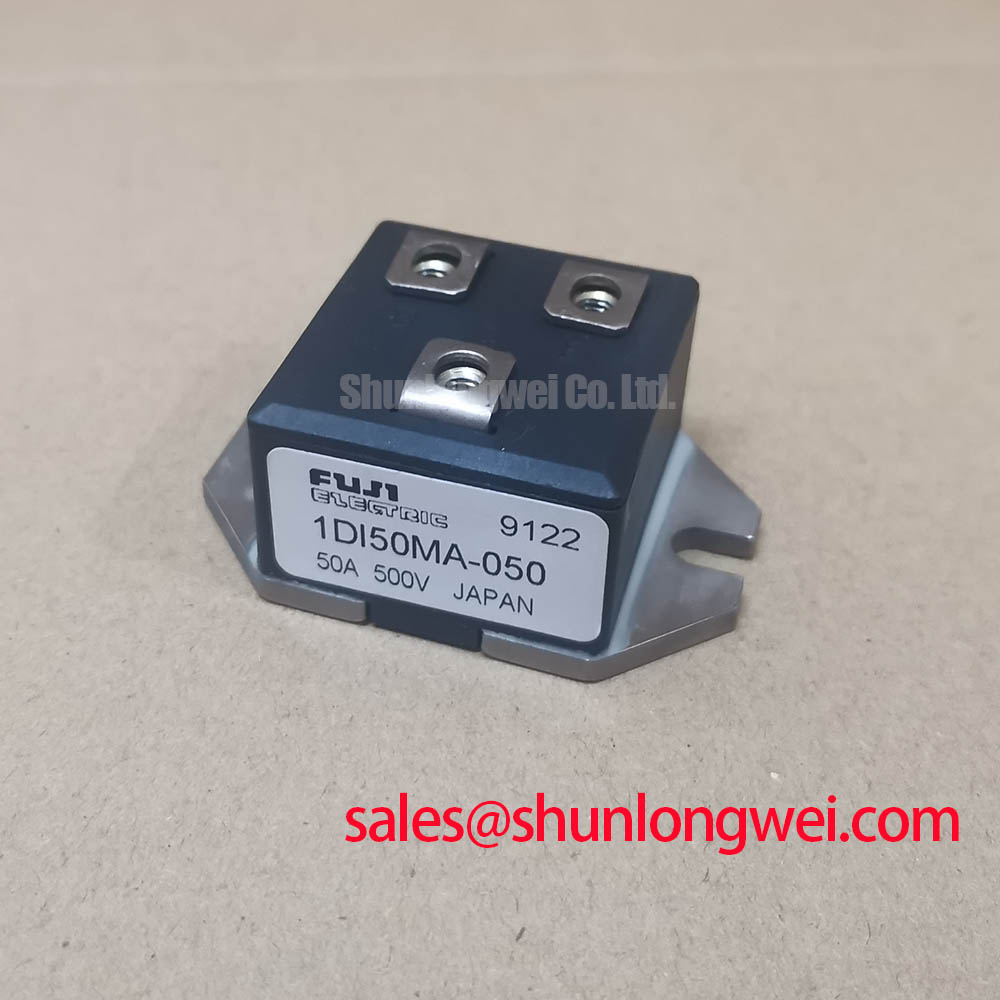

Technical Analysis for System Integration
The standout feature of the 1DI50MA-050 module is its high DC current gain (hFE), with a specified minimum of 100. This high gain is a direct result of its Darlington pair configuration. For a design engineer, this translates to a significantly lower base current requirement to achieve the maximum collector current of 50A. This simplification of the gate drive circuit reduces complexity, component count, and power consumption in the control stage. Think of hFE as a leverage ratio for current; a high value means a small input effort (base current) can precisely control a much larger output force (collector current).
Another critical design element is the module’s integrated electrical isolation. The baseplate is isolated from the transistor terminals, rated to withstand 2500V AC for one minute. This feature is crucial for safety and assembly efficiency. It allows the module to be mounted directly onto a grounded chassis or heatsink without needing external insulating pads, which can impede thermal transfer. This direct mounting path improves thermal management, ensuring heat generated during operation is dissipated more effectively, which is fundamental to long-term reliability.
Optimized Application Scenarios
The specifications of the 1DI50MA-050 make it a strong candidate for several industrial power conversion systems:
- DC Motor Controllers: Its 50A current capability and robust voltage ratings are well-suited for controlling the speed and torque of medium-sized DC motors.
- Switching Power Supplies: The module can serve as the primary switching element in high-power buck or boost converters.
- General-Purpose Inverters: Useful in the power stage of inverters where straightforward control and reliable performance are primary requirements.
- Solenoid and Relay Drivers: The high gain simplifies the interface with microcontrollers for driving high-current inductive loads.
This module is best matched for industrial systems requiring robust, straightforward current control up to 50A without complex drive architectures.
Key Specifications of the 1DI50MA-050
| Absolute Maximum Ratings (at Tc=25°C) | |
|---|---|
| Collector-Base Voltage (VCBO) | 600 V |
| Collector-Emitter Voltage (VCEO) | 500 V |
| Emitter-Base Voltage (VEBO) | 10 V |
| DC Collector Current (IC) | 50 A |
| DC Base Current (IB) | 2 A |
| Collector Power Dissipation (PC) | 310 W |
| Operating Junction Temperature (Tj) | +150 °C |
| Electrical Characteristics (at Tc=25°C unless otherwise noted) | |
| Collector-Emitter Saturation Voltage (VCE(sat)) | 2.0 V max. (at IC=50A, IB=0.5A) |
| Base-Emitter Saturation Voltage (VBE(sat)) | 2.5 V max. (at IC=50A, IB=0.5A) |
| DC Current Gain (hFE) | 100 min. (at IC=50A, VCE=2V) |
| Collector Cut-off Current (ICBO) | 1.0 mA max. (at VCB=500V) |
| Isolation Voltage (Visol) | 2500 V (AC, 1 minute) |
Engineer’s FAQ for the 1DI50MA-050
How does the high hFE of the 1DI50MA-050 simplify the drive circuit design?
A high DC current gain (hFE), with a minimum of 100, means the module requires only a small base current to switch a large collector current. For example, to switch the full 50A, the required base current is only around 0.5A. This allows for a less powerful, less complex, and more cost-effective driver stage compared to transistors with lower gain.
What are the key considerations when mounting this module to a heatsink?
Thanks to its 2500V isolated baseplate, the 1DI50MA-050 can be mounted directly to a grounded heatsink without extra insulating washers. For effective heat transfer, ensure the mounting surface is flat and clean. Apply a thin, even layer of thermal compound before securing the module with the recommended torque for the mounting screws to avoid mechanical stress and ensure optimal thermal contact.
What is the benefit of the Darlington configuration in this module?
The internal Darlington configuration connects two bipolar junction transistors (BJTs) in a way that the current amplified by the first transistor is further amplified by the second. The result is a much higher overall current gain (hFE) than a single transistor could provide. This makes the device easier to drive, which is a primary advantage in power semiconductors.
Is the 1DI50MA-050 suitable for high-frequency applications?
The 1DI50MA-050 is a Darlington transistor, which inherently has slower switching speeds compared to single transistors or modern IGBTs and MOSFETs. The datasheet specifies rise, storage, and fall times that suggest it is best suited for low-frequency applications, such as motor control and power supplies operating in the low kilohertz range. It is not intended for high-frequency inverters.
Enabling Robust Power Control
The 1DI50MA-050 power transistor module offers a direct path to implementing reliable control in medium-power systems. By delivering high current gain in an electrically isolated package, it empowers engineers to develop simplified, cost-effective, and thermally efficient designs for a range of industrial applications.