Fuji 2MBI600NT-060: A Technical Analysis of a Robust 600A IGBT Module
Fuji 2MBI600NT-060: 600V 600A Dual IGBT Module Analysis
High-Current Performance with Proven N-Series Reliability
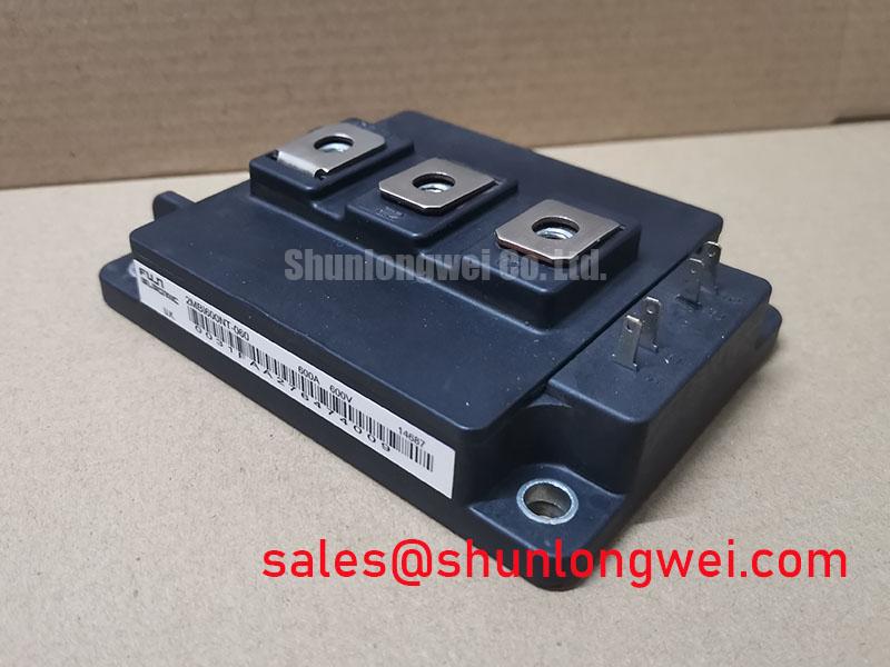
The Fuji Electric 2MBI600NT-060 is a dual IGBT module providing a robust 600V, 600A half-bridge configuration for high-power switching applications. Its unique value stems from combining a high current capacity with the proven reliability of Fuji’s N-series platform and effective thermal performance. This makes it a dependable building block for demanding power conversion systems.
- Core Specifications: 600V | 600A | VCE(sat) 2.1V (typ)
- Key Advantages: Facilitates efficient thermal management, ensures robust performance under heavy loads.
For engineers designing high-power motor drives, the module’s ability to maintain a low saturation voltage at its maximum rated current directly translates to lower conduction losses and reduced thermal stress on the entire system. Explore the root causes of IGBT failures to understand how robust design mitigates risk.
Download the Official 2MBI600NT-060 Datasheet (PDF)

Technical Analysis for Power System Design
The engineering value of the 2MBI600NT-060 lies in its balance of high current capability and thermal efficiency. The module is specified for a continuous collector current (Ic) of 600A, making it a suitable component for inverter legs in systems driving large industrial motors or serving high-capacity power supplies. The internal configuration of two IGBTs in a half-bridge simplifies the layout of three-phase inverters, requiring just three modules for a complete B6 bridge.
A critical parameter for high-current modules is the thermal resistance from junction to case (Rth(j-c)). For this device, the datasheet specifies a low typical value of 0.05°C/W for the IGBT. This figure is essential for thermal design. You can think of thermal resistance like the width of a pipe; a lower value represents a wider pipe, allowing heat to flow more easily from the active silicon to the heatsink. This efficient heat extraction is vital for maintaining the junction temperature below the maximum limit of 150°C, ensuring operational stability and longevity. Proper IGBT thermal design is fundamental to system reliability.
Optimized Application Scenarios
The specifications of the 2MBI600NT-060 make it a strong candidate for several high-power industrial applications:
- AC Motor Controls & VFDs: The 600A current rating is well-suited for controlling large three-phase induction motors where high torque and variable speed are required.
- Uninterruptible Power Supplies (UPS): Its robust performance and square Reverse Bias Safe Operating Area (RBSOA) ensure reliable switching during grid-to-battery transitions in high-capacity UPS systems.
- Welding Power Supplies: The module’s ability to handle high pulse currents (up to 1200A) makes it suitable for the demanding load cycles found in industrial welding equipment.
- High-Power DC-DC Converters: As a fundamental half-bridge building block, it can be used in various high-current converter topologies for applications like battery charging or bulk power conversion.
This module is best matched for systems requiring a durable, high-current 600V switching block where straightforward and effective thermal management is a priority.
Key Specifications of the 2MBI600NT-060
| Parameter | Symbol | Value | Conditions |
|---|---|---|---|
| Absolute Maximum Ratings (Tc=25°C) | |||
| Collector-Emitter Voltage | VCES | 600V | |
| Gate-Emitter Voltage | VGES | ±20V | |
| Continuous Collector Current | IC | 600A | Tc=80°C |
| Peak Collector Current | ICP | 1200A | 1ms pulse |
| Max. Power Dissipation | PC | 2500W | Per IGBT |
| Electrical Characteristics (Tj=125°C unless otherwise specified) | |||
| Collector-Emitter Saturation Voltage | VCE(sat) | 2.1V (Typ.) / 2.7V (Max.) | IC=600A, VGE=15V |
| Gate-Emitter Threshold Voltage | VGE(th) | 4.0V to 7.5V | Tj=25°C, VCE=20V, IC=600mA |
| Diode Forward Voltage | VF | 2.2V (Typ.) / 2.8V (Max.) | IF=600A, VGE=0V |
| Thermal Characteristics | |||
| Thermal Resistance (Junction-to-Case) | Rth(j-c) | 0.05 °C/W (IGBT), 0.11 °C/W (Diode) | |
Engineer’s FAQ for the 2MBI600NT-060
What is the primary consideration for thermal design when using the 2MBI600NT-060?
The main task is selecting a heatsink that can dissipate the calculated power loss while keeping the IGBT junction temperature below its 150°C maximum. Using the Rth(j-c) value of 0.05°C/W for the IGBT and the Rth(c-f) (case-to-fin) of your thermal interface material, you can determine the required heatsink-to-ambient thermal resistance for your worst-case power dissipation scenario.
How should this module be mounted to ensure good thermal contact?
The datasheet recommends a mounting screw torque of 2.5 to 3.5 N·m. It’s critical to apply a thin, even layer of thermal compound to ensure a void-free interface between the module’s baseplate and the heatsink. Uneven pressure or improper compound application can significantly increase thermal resistance and lead to overheating.
What is the recommended gate drive voltage?
For optimal performance, a +15V gate-emitter voltage is typically used for turn-on, and a negative voltage (e.g., -5V to -15V) is recommended for turn-off to ensure immunity to noise and parasitic turn-on. The absolute maximum VGES rating is ±20V. Understanding robust gate drive design is essential for reliability.
Is the 2MBI600NT-060 suitable for high-frequency applications?
This N-series module is optimized for low conduction losses rather than ultra-fast switching. Its switching times (turn-on typically 0.6µs, turn-off typically 0.6µs at 25°C) make it best suited for lower-frequency applications like motor drives and UPS systems, typically operating in the range of a few kilohertz. For applications above 20kHz, a module with lower switching energy (Eon/Eoff) would be a more appropriate choice.
Enabling Robust High-Power Conversion
The 2MBI600NT-060 IGBT module provides a solid foundation for high-current power stages. By leveraging a low on-state voltage and effective thermal transfer, it allows engineers to develop reliable and efficient power conversion systems. Its straightforward, half-bridge design serves as a versatile component for a wide array of industrial applications where durability and high-current handling are key design criteria.