Mitsubishi CM450DX-24S1 IGBT Module: A Comprehensive Technical Review
Mitsubishi CM450DX-24S1 IGBT Module | 1200V 450A Dual
Technical Analysis of the CM450DX-24S1 S-Series IGBT Module
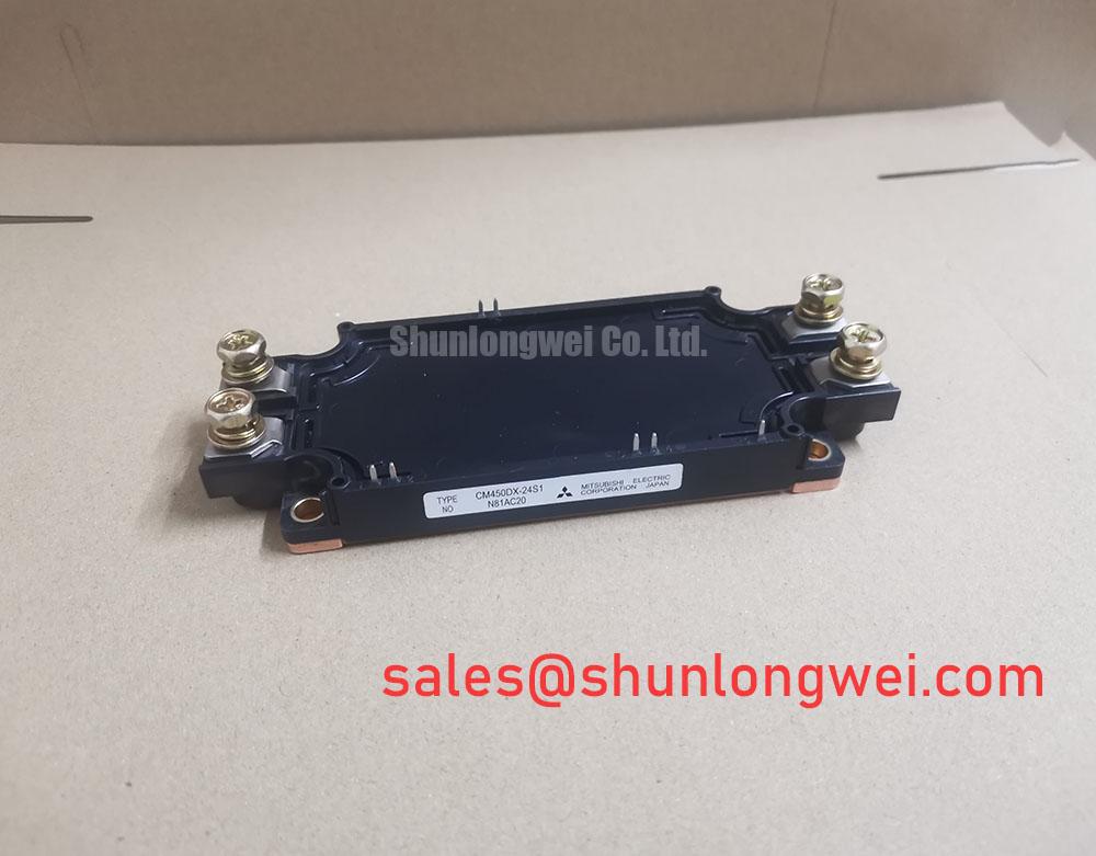
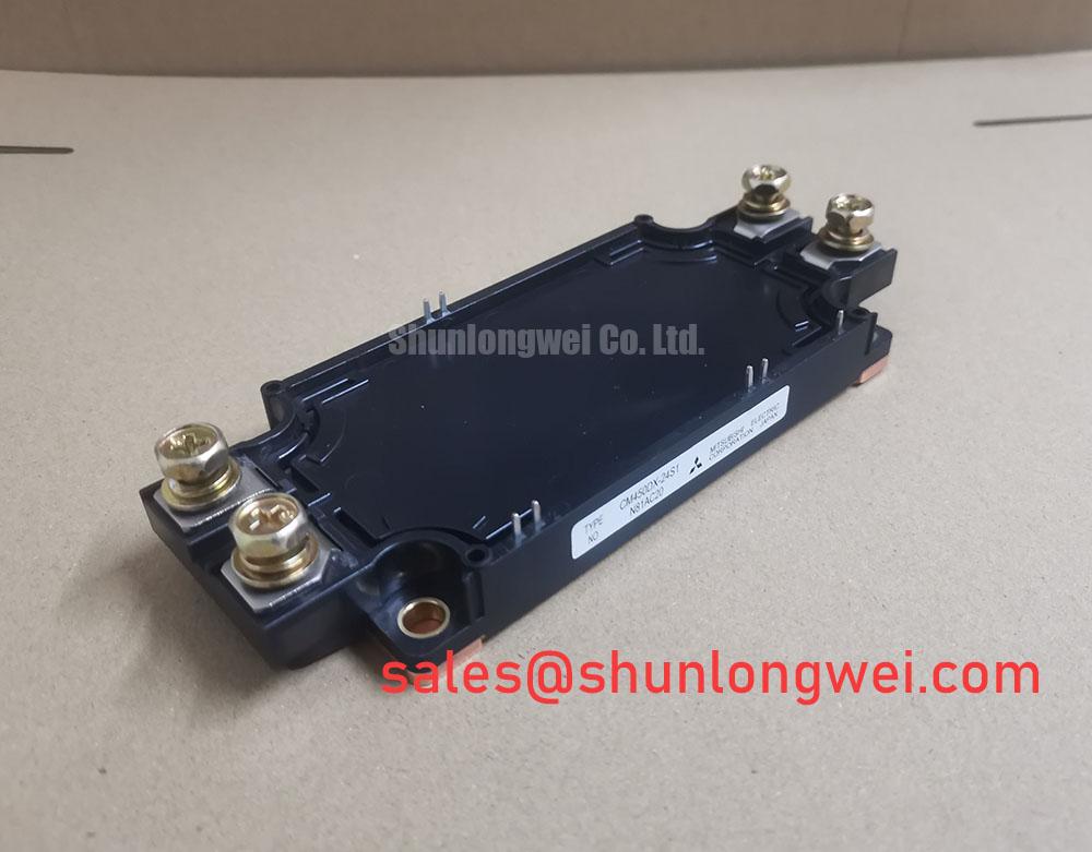
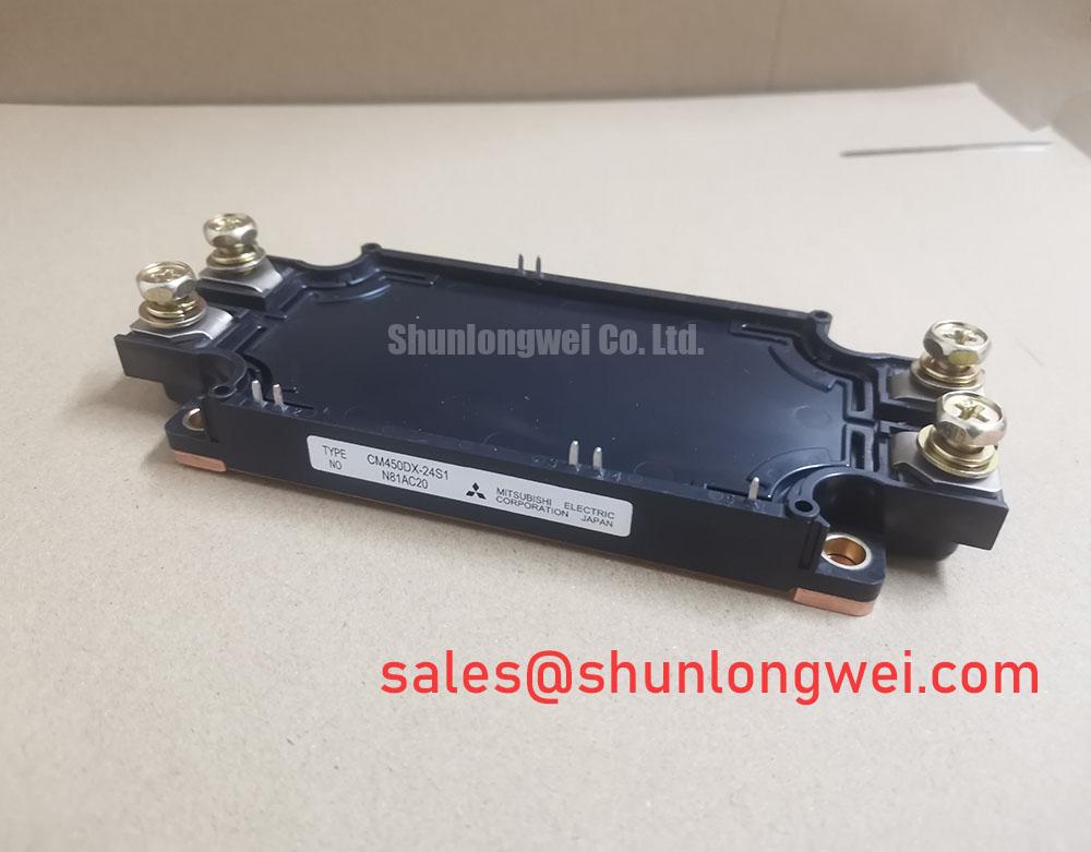
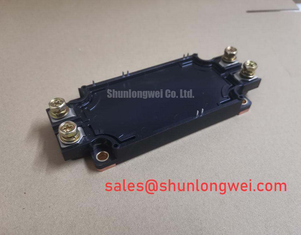
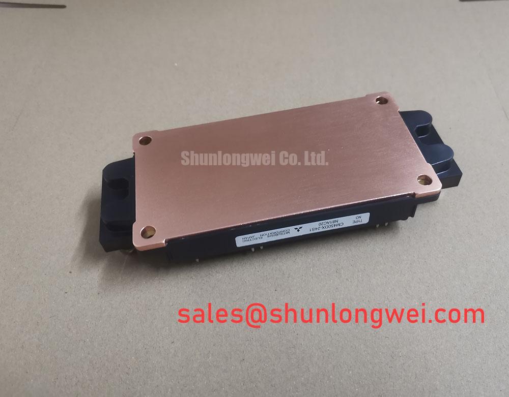
The Mitsubishi CM450DX-24S1 is a dual IGBT module from the S-Series, offering a robust 1200V blocking voltage and a 450A collector current rating. This module is engineered to provide a balanced solution for high-power switching applications by leveraging Mitsubishi’s CSTBT™ (Carrier Stored Trench-gate Bipolar Transistor) technology. This design approach focuses on achieving low conduction losses while maintaining controlled switching characteristics to ensure system reliability.
- Core Specifications: 1200V | 450A | VCE(sat) 2.40V (max)
- Key Features: Low conduction loss via CSTBT™ chip, integrated NTC for temperature sensing.
- Engineering Value: Enables efficient power conversion and provides critical thermal feedback for system protection.
For engineers designing high-power inverters, the module’s performance characteristics facilitate effective thermal management and contribute to overall system longevity. Download the Official CM450DX-24S1 Datasheet (PDF)
A Deeper Look at Performance Metrics
A key performance indicator for this module is its collector-emitter saturation voltage, VCE(sat), which has a maximum value of 2.40V at its nominal current (450A) and a junction temperature of 125°C. This parameter is a direct result of the CSTBT™ silicon design, which optimizes the trade-off between on-state voltage and switching speed. A lower VCE(sat) value is crucial as it directly reduces the power lost as heat during conduction phases. This efficiency gain helps to simplify the cooling system requirements. For further reading, see this guide on the quest for lower IGBT VCE(sat).
Effective thermal management is fundamental to the reliability of any power system. The CM450DX-24S1 datasheet specifies the thermal resistance from junction to case (Rth(j-c)) for the IGBT as 0.056 °C/W (or 54 K/kW in the datasheet’s notation). This value can be thought of as the width of a pipe for heat dissipation; a lower number signifies a wider pipe, allowing heat to escape more easily from the active silicon to the heatsink. A low thermal resistance is critical for preventing the device from exceeding its maximum operating junction temperature of 150°C under continuous operation. Combining this with an appropriate heatsink is essential for preventing common IGBT failure modes related to overheating.
Optimized Application Scenarios
The CM450DX-24S1 is well-suited for several high-power industrial applications, where its specifications provide distinct advantages:
- AC Motor Control & VFDs: The dual-switch (half-bridge) configuration and 450A current rating are ideal for building three-phase inverters for variable frequency drives.
- Motion/Servo Control: Its controlled switching characteristics help manage EMI, while the fast-recovery freewheeling diode (FWD) is beneficial for systems with inductive loads.
- Uninterruptible Power Supplies (UPS): The module’s robust short-circuit withstand time of at least 10µs provides a critical safety margin needed in UPS applications to handle fault conditions without catastrophic failure.
This module is best matched for systems requiring a balance of high power capacity, proven reliability, and straightforward thermal design.
Key Specifications of the CM450DX-24S1
| Parameter | Symbol | Value | Conditions |
|---|---|---|---|
| Absolute Maximum Ratings (Tj=25°C) | |||
| Collector-Emitter Voltage | VCES | 1200V | VGE = 0V |
| Gate-Emitter Voltage | VGES | ±20V | VCE = 0V |
| Collector Current (DC) | IC | 450A | TC = 107°C |
| Collector Current (Pulse) | ICRM | 900A | Repetitive pulse |
| Isolation Voltage | Visol | 4000V | RMS, f=60Hz, AC 1 min |
| Electrical & Thermal Characteristics (Tj=125°C unless noted) | |||
| Collector-Emitter Saturation Voltage | VCE(sat) | 1.95V (typ), 2.40V (max) | IC = 450A, VGE = 15V |
| Gate-Emitter Threshold Voltage | VGE(th) | 5.5V to 7.5V | IC = 45mA, VCE = 10V |
| Thermal Resistance (IGBT, Junction-to-Case) | Rth(j-c)Q | 0.056 °C/W (max) | Per 1/2 module |
| Thermal Resistance (Diode, Junction-to-Case) | Rth(j-c)D | 0.086 °C/W (max) | Per 1/2 module |
Engineer’s FAQ
- How does VCE(sat) impact system efficiency?
- VCE(sat) is the on-state voltage drop across the IGBT. Power loss during conduction is calculated as VCE(sat) multiplied by the collector current. A lower VCE(sat), like the 2.40V maximum for the CM450DX-24S1, means less energy is wasted as heat, leading to higher inverter efficiency and reduced cooling requirements.
- What are the recommended mounting torque settings?
- According to the datasheet, the main terminals (M6 screws) should be tightened to a torque of 3.5 to 4.5 N·m. For mounting the module to a heatsink, the recommended torque for the mounting screws (M6) is also 3.5 to 4.5 N·m. Proper torque is crucial for ensuring low thermal and electrical resistance.
- How is the module’s temperature monitored?
- The CM450DX-24S1 includes an integrated NTC (Negative Temperature Coefficient) thermistor. This allows the control system to monitor the module’s approximate temperature in real-time, enabling over-temperature protection and supporting advanced thermal management strategies.
- What is the recommended gate-emitter voltage (VGE) for operation?
- The datasheet specifies electrical characteristics based on a recommended VGE of +15V for turning the IGBT on. The absolute maximum gate-emitter voltage is ±20V. Operating within the recommended range ensures optimal performance and prevents damage to the gate structure.
The CM450DX-24S1 presents a well-documented, reliable component for engineers developing or maintaining high-power systems. Its blend of efficient CSTBT™ technology and a robust thermal design provides a dependable foundation for industrial power conversion applications.