Toshiba MG100J7KS50: An Integrated 7-in-1 Power Module for Motor Control
Toshiba MG100J7KS50 600V 100A GTR Module
Integrated 7-in-1 Power Stage for Motor Control
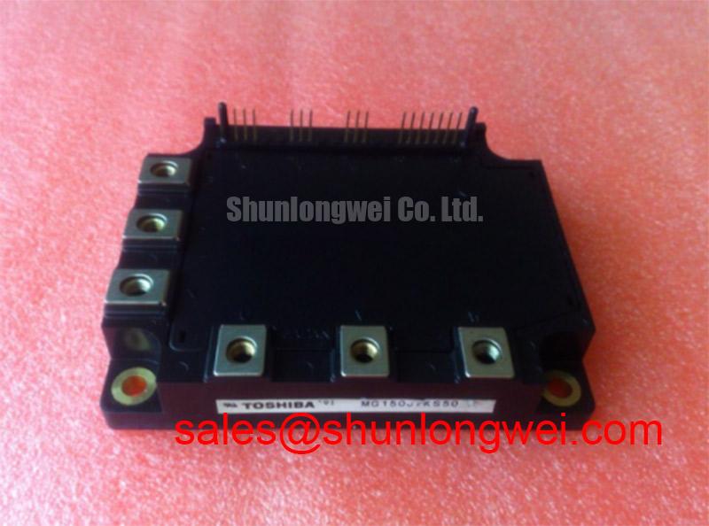
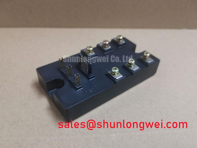
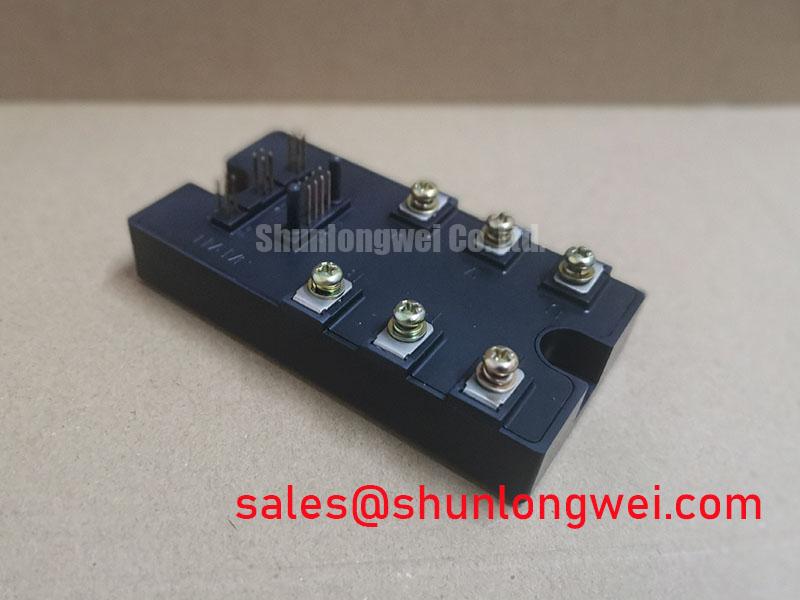
The Toshiba MG100J7KS50 is a Silicon N-Channel GTR (Giant Transistor) module that integrates seven IGBTs into a single package. This configuration includes a three-phase converter, a three-phase inverter, and a brake transistor, providing a comprehensive power stage for AC motor control applications. The module’s design focuses on simplifying system assembly and improving thermal management in variable frequency drives and general-purpose inverters.
- Core Specifications: 600V | 100A | VCE(sat) of 2.5V (max)
- Key Advantages: Reduces component count, simplifies PCB layout, and provides an electrically isolated case for flexible mounting.
By combining the rectifier, inverter, and brake functions, the MG100J7KS50 allows engineers to reduce the physical footprint and complexity of their power conversion systems.
Download the Official Datasheet (PDF)
Technical Analysis: Integration and Performance
The primary value of the MG100J7KS50 lies in its high level of integration. Consolidating a three-phase diode bridge rectifier, a three-phase inverter, and a dynamic braking chopper into one module significantly streamlines the design process for motor drives. This approach minimizes stray inductance between stages, a common challenge in systems built from PIM vs discrete IGBT components, leading to more predictable switching performance and reduced EMI generation.
Efficient thermal management is critical in power applications. The module’s thermal resistance, Rth(j-c), can be thought of as the width of a pathway for heat to travel from the active semiconductor junction to the case. With a junction-to-case thermal resistance of 1.56 °C/W for the IGBTs and 2.00 °C/W for the diodes, this module offers a defined path for heat extraction. This allows for straightforward heatsink selection and helps ensure the device operates within its safe temperature limits, a key factor in long-term reliability.
The collector-emitter saturation voltage (VCE(sat)) is a direct contributor to conduction losses. The MG100J7KS50 specifies a maximum VCE(sat) of 2.5V at its rated current of 100A. While not the lowest in its class, this value represents a balance between conduction losses and the switching performance necessary for motor control frequencies. This balance is crucial for managing overall system efficiency and thermal load. For further reading, see the analysis of how the free-wheeling diode dictates system performance.
Optimized Application Scenarios
- Variable Frequency Drives (VFDs): The all-in-one CIB configuration is purpose-built for VFDs, containing all necessary power stages for converting AC line voltage to a variable frequency output for motor speed control.
- General Purpose Inverters: The 100A current rating and 600V blocking voltage make it suitable for a range of industrial inverter applications where a compact and reliable power core is needed.
- Servo Drives: In applications requiring precise motor positioning, the integrated brake chopper provides the necessary dynamic braking capability to handle regenerative energy, simplifying the overall drive design.
The integrated nature of this module makes it an optimal match for applications where reducing assembly time and system size are primary design goals.
Key Specifications of the MG100J7KS50
| Absolute Maximum Ratings | |||
|---|---|---|---|
| Collector-Emitter Voltage (VCES) | 600 V | Gate-Emitter Voltage (VGES) | ±20 V |
| Collector Current (DC) (IC) | 100 A | Collector Power Dissipation (PC) | 320 W |
| Junction Temperature (Tj) | 150 °C | VRM (Repetitive Peak Reverse Voltage) | 600 V |
| Electrical Characteristics (Inverter Stage at Tj=25°C) | |||
| Collector-Emitter Saturation Voltage (VCE(sat)) | 2.5 V (max) @ IC = 100A | Gate-Emitter Leakage Current (IGES) | ±500 nA (max) @ VGE = ±20V |
| Turn-off Time (toff) | 1.0 µs (typ) | Diode Forward Voltage (VECF) | 2.5 V (max) @ IEC = 100A |
| Thermal and Mechanical Specifications | |||
| Thermal Resistance, Junction to Case (Rth(j-c) – IGBT) | 1.56 °C/W (max) | Mounting Torque (Terminals) | 1.96 ± 0.2 N·m |
Engineer’s FAQ
What are the main advantages of using an integrated CIB module like the MG100J7KS50?
The primary advantage is system simplification. It combines the AC-DC rectifier, DC-AC inverter, and braking chopper into one component. This reduces the bill of materials (BOM), minimizes PCB layout complexity, shortens assembly time, and can lower the overall system cost compared to using discrete devices for each function.
What is the recommended mounting torque for the MG100J7KS50, and why is it critical?
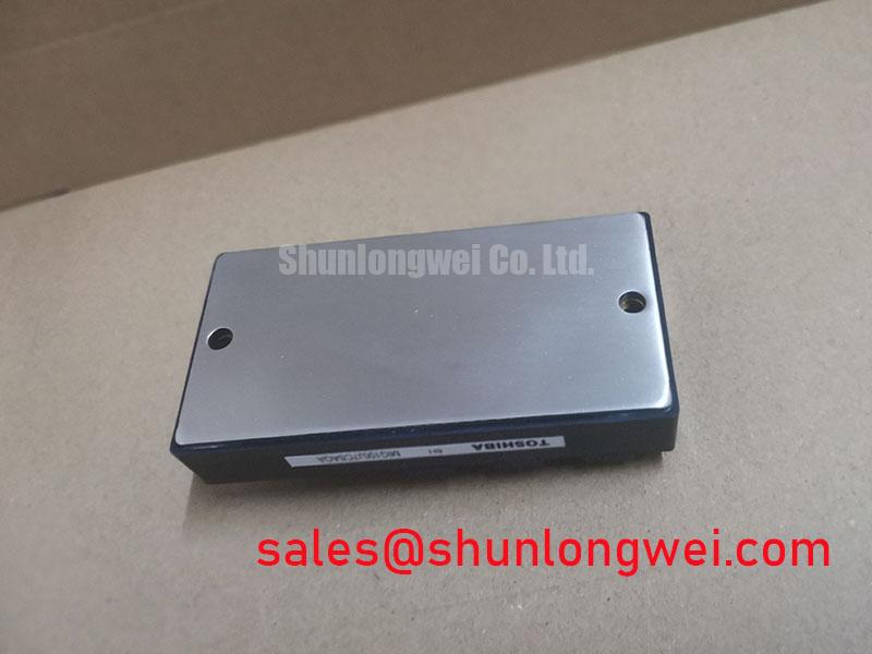
The datasheet specifies a terminal mounting torque of 1.96 ± 0.2 N·m and a heatsink mounting torque of 2.94 ± 0.29 N·m. Adhering to these values is crucial. Overtightening can cause mechanical stress, cracking the ceramic substrate and leading to isolation failure. Undertightening results in poor thermal contact with the heatsink, causing the device to overheat and fail prematurely. Proper torque ensures both effective thermal dissipation and mechanical integrity.
What is the function of the brake unit in this module?
The brake unit, consisting of an IGBT and a freewheeling diode, is used for dynamic braking. When an AC motor decelerates, it acts as a generator, sending power back to the DC bus. The brake chopper dissipates this regenerative energy as heat through an external resistor, preventing DC bus overvoltage and protecting the inverter stage.
Are the mounting terminals electrically isolated?
Yes, the datasheet states that the electrodes are isolated from the case. This provides an electrical isolation barrier, simplifying mounting procedures as the heatsink does not need to be isolated from the system chassis, which can be beneficial for grounding and EMI management.
Design and Application Notes
The MG100J7KS50 integrates the fundamental building blocks of a motor drive into a single, thermally manageable package. This consolidation provides a direct path to developing compact and reliable power conversion systems. Its balanced electrical characteristics support efficient operation in the frequency ranges typically found in industrial automation, empowering engineers to meet performance targets with a simplified hardware design.