Mitsubishi PM600DSA060-04: 600V 600A Dual Intelligent Power Module with Integrated Protection
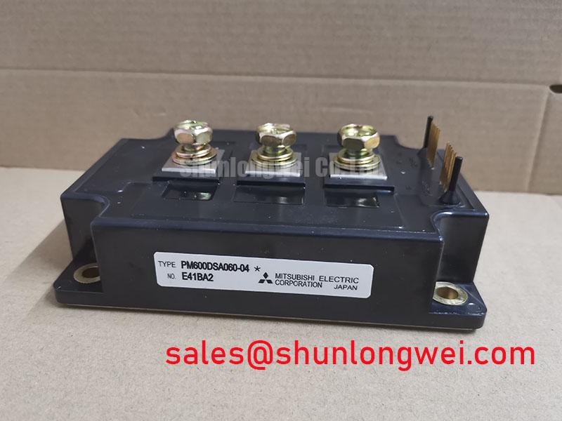
Mitsubishi PM600DSA060-04 Intelligent Power Module (IPM) 600V 600A
Advanced Dual-Phase Switching with Integrated Protection Logic
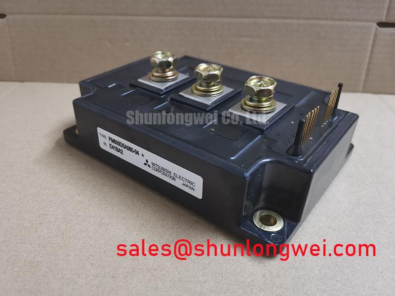
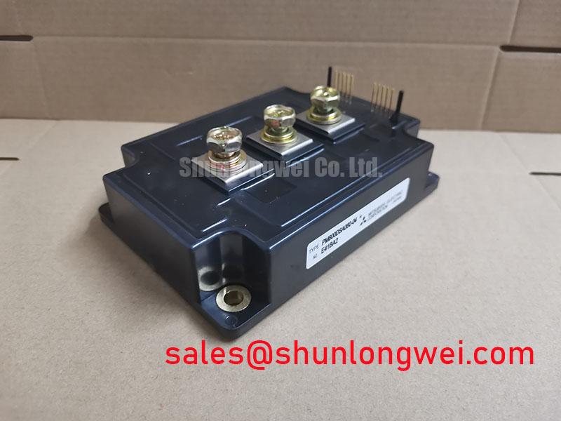
The Mitsubishi PM600DSA060-04 is a high-power, flat-base type Intelligent Power Module (IPM) engineered for demanding industrial power conversion. By integrating a dual-phase IGBT bridge with dedicated gate drive circuitry and a comprehensive suite of protection logic, this module establishes a unique value proposition: the elimination of external protection design complexity while maintaining superior current density. This module is characterized by its 600V collector-emitter voltage and 600A continuous current rating, making it a cornerstone for large-scale power systems.
- Core Specifications: 600V | 600A | 2500V Isolation Voltage
- Key Advantages: Reduced parasitic inductance via flat-base packaging; integrated protection circuitry reduces development time.
One common concern for power engineers is how to maintain signal integrity in high-current environments. The PM600DSA060-04 addresses this through internal opto-coupler isolation interfaces and logic-level control, which effectively shields the control stage from high-voltage noise generated at the 600A switching level.
Download Official Datasheet (PDF)

Technical Analysis of Integrated Protection and Thermal Management
The PM600DSA060-04 transcends standard power modules by embedding “intelligence” directly at the silicon level. The module features built-in Over-Current (OC), Short-Circuit (SC), Over-Temperature (OT), and Under-Voltage Lockout (UV) protections. This integration is critical because traditional discrete designs often suffer from latency between the fault sensing and the driver response. In this module, the protection logic acts like a localized reflex system—much like how the human spinal cord can react to heat before the brain processes the pain—allowing the module to shut down within microseconds of an SC event, effectively preserving the device’s lifespan.
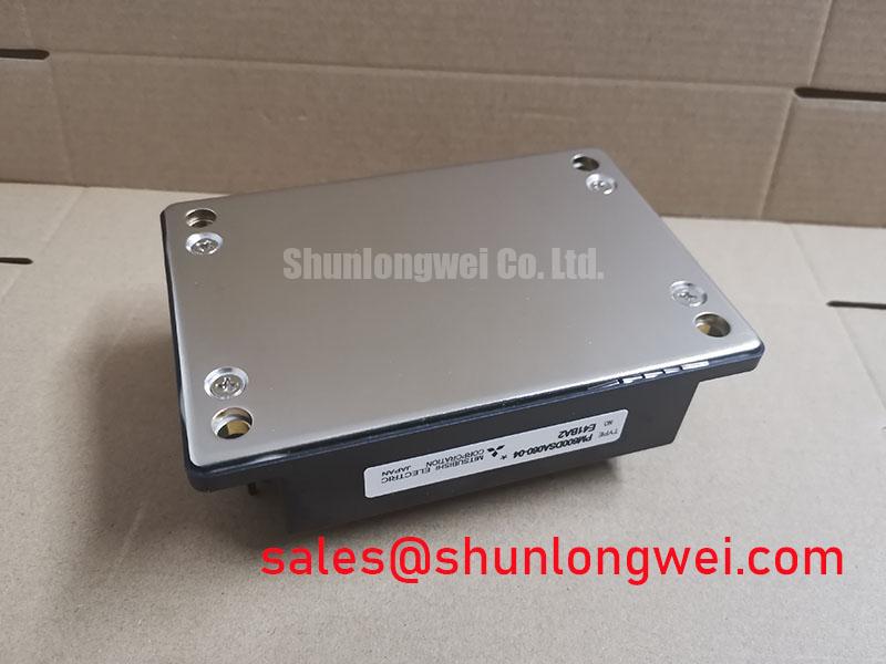
Thermal resistance is another pivotal parameter. With a junction-to-case thermal resistance ($R_{th(j-c)}$) of only 0.04°C/W for the IGBT portion, the PM600DSA060-04 facilitates rapid heat transfer to the heatsink. To visualize this, consider thermal resistance as the width of a highway; a lower value represents a wider road that allows a higher volume of heat “traffic” to flow away from the sensitive silicon die without causing a bottleneck or “thermal pile-up.” This low resistance is essential for maintaining a stable junction temperature when switching 600A loads.
Optimized Application Scenarios
The engineering profile of the PM600DSA060-04 makes it particularly suited for applications requiring high reliability and high power density:
- Large-Scale Variable Frequency Drives (VFDs): The module’s low $V_{CE(sat)}$ (typically 1.8V) minimizes conduction losses, which is vital for the energy efficiency of industrial motor control systems.
- Uninterruptible Power Supplies (UPS): Fast switching capability combined with integrated overvoltage protection ensures grid-quality power output.
- Solar Inverters: The 600V rating is ideal for mid-voltage DC bus architectures, where the dual-phase structure simplifies H-bridge implementation.
- Welding Power Supplies: High ruggedness against current surges is provided by the internal short-circuit protection.
The PM600DSA060-04 is the best match for systems where minimizing the physical footprint of the inverter stage is a primary design objective.
Key Specification Parameters
| Parameter Group | Specification | Value (Typ/Max) |
|---|---|---|
| Absolute Maximum Ratings | Collector-Emitter Voltage ($V_{CES}$) | 600V |
| Collector Current Continuous ($I_C$) | 600A | |
| Isolation Voltage ($V_{iso}$) | 2500V AC | |
| Electrical Characteristics | Saturation Voltage ($V_{CE(sat)}$) | 1.8V (Typ) / 2.7V (Max) |
| Diode Forward Voltage ($V_{EC}$) | 2.2V (Typ) | |
| Thermal Characteristics | Thermal Resistance (IGBT) | 0.04°C/W |
| Thermal Resistance (FWDi) | 0.07°C/W |
Engineer FAQ: Implementation and Design Challenges
Q1: How should the fault output signal ($F_o$) be utilized in a system-level safety architecture?
The $F_o$ pin is an open-collector output that pulls low when an internal protection event occurs (OC, SC, OT, or UV). Engineers should connect this to the system controller’s interrupt pin with a pull-up resistor to trigger an immediate global stop of PWM signals across all modules.
Q2: What is the recommended power supply voltage for the control logic?
The internal gate drive logic requires a stable $V_D$ of 15V. Variations beyond ±1.5V may trigger the under-voltage protection mechanism, ensuring the IGBTs are never driven in an incomplete linear region that would cause catastrophic overheating.
Q3: How do the flat-base design and mounting torque affect thermal performance?
Unlike conventional modules, the flat-base structure eliminates internal mounting stress. However, precise terminal and mounting torque is essential. For the PM600DSA060-04, the mounting screws should be tightened to the datasheet-specified 2.5–3.5 N·m to ensure uniform thermal contact without deforming the baseplate.
By integrating high-speed IGBT technology with a hardened control layer, the PM600DSA060-04 allows engineers to focus on system-level optimization rather than low-level protection circuitry. Its robust thermal interface and massive current capacity provide a stable foundation for the most demanding high-power industrial designs.