Infineon FP25R12W2T4_B11 EasyPIM™ 2B 1200V 25A IGBT Module: Technical Overview and Applications
Infineon FP25R12W2T4_B11 EasyPIM™ 2B 1200V 25A IGBT Module
Introduction and Core Technical Highlights
The FP25R12W2T4_B11 is a highly integrated Power Integrated Module (PIM) from Infineon’s EasyPIM™ 2B family, featuring the robust TRENCHSTOP™ IGBT4 technology. This module provides a complete power stage in a single compact footprint, incorporating a three-phase bridge rectifier, a three-phase inverter, a brake chopper, and an integrated NTC thermistor for precise thermal monitoring. It is specifically engineered to reduce system complexity while maintaining high efficiency in low-to-medium power industrial applications.
- Core Ratings: 1200V Blocking Voltage | 25A Continuous DC Collector Current ($T_C = 100^circ C$) | 10µs Short-Circuit Withstand Time
- Engineering Advantages: Optimized switching losses for high-frequency operation and PressFIT pins for solderless, reliable mounting.
- Design Intent: Effectively answers the requirement for high power density in space-constrained power semiconductors assemblies.
Download Official Datasheet (PDF)
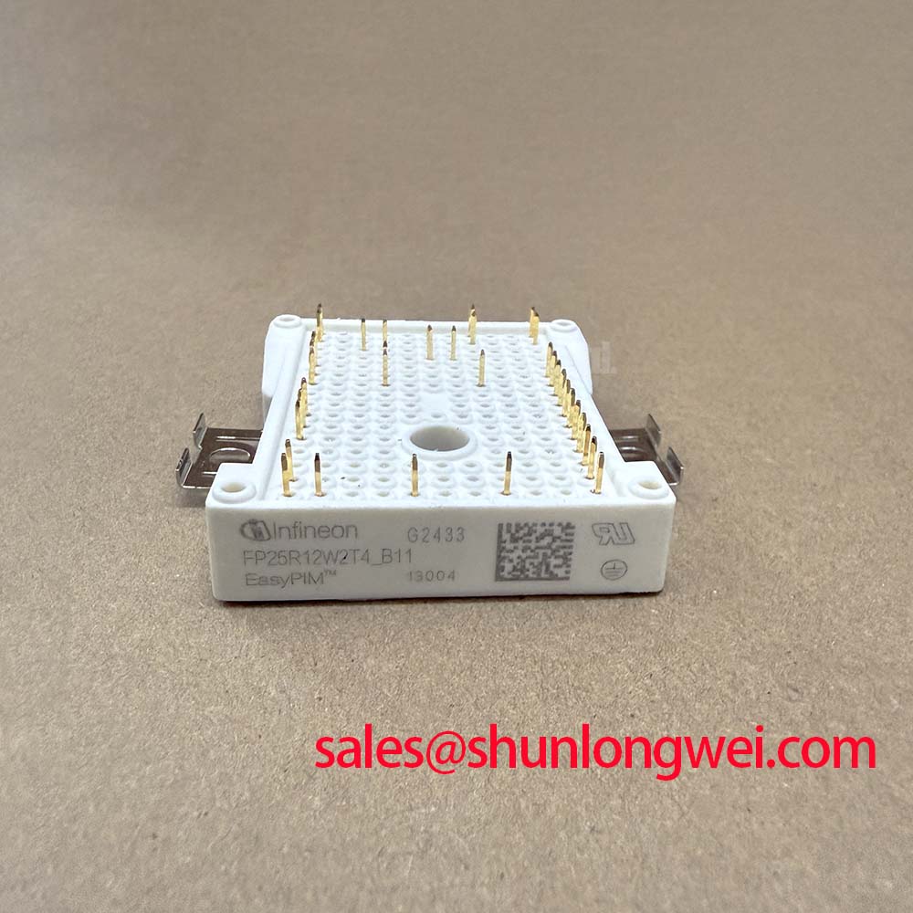
M3: Technical Analysis of TRENCHSTOP™ IGBT4 Implementation
The FP25R12W2T4_B11 utilizes the Trenchstop IGBT4 architecture, which is pivotal in achieving a low saturation voltage ($V_{CE(sat)}$) of typically 1.85V at 25A ($T_{vj} = 25^circ C$). This architectural choice directly minimizes conduction losses, which is critical for maintaining thermal stability under continuous heavy loads. The inclusion of a dedicated brake chopper allows for controlled energy dissipation during regenerative braking, safeguarding the DC link capacitor bank in motor drive configurations.
One of the module’s most significant engineering parameters is its 10µs short-circuit withstand capability at $T_{vj} = 150^circ C$. To understand its importance, one can compare short-circuit withstand time to the reaction time of a safety fuse; a longer 10µs window provides the gate driver circuit more time to detect a fault and safely shut down the module before catastrophic thermal failure occurs. This inherent ruggedness significantly enhances the overall system reliability in harsh industrial environments.
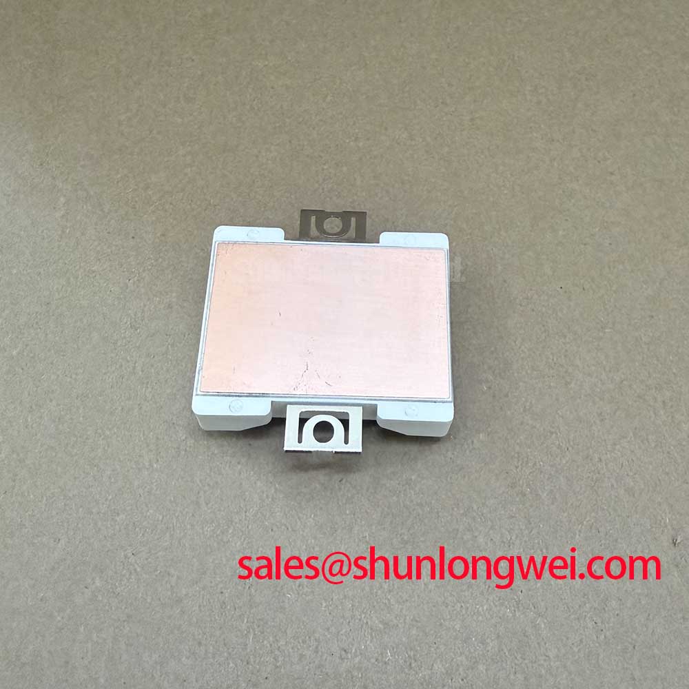
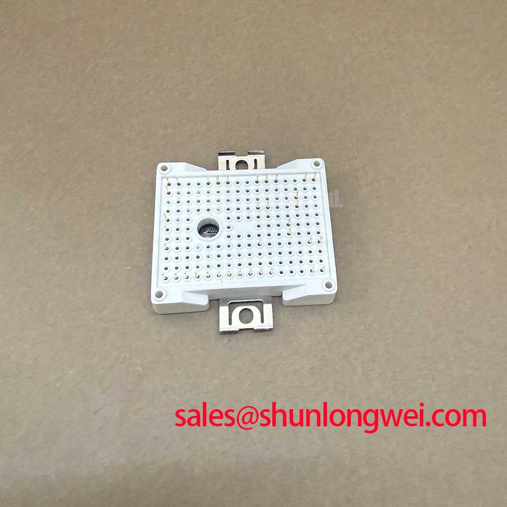
Optimized Application Scenarios
The FP25R12W2T4_B11 is optimized for several industrial sectors where the PIM vs Discrete debate is settled by the need for integration and reliability:
- Compact Motor Drives: The integrated rectifier and inverter stages allow for significant PCB area savings in variable frequency drives (VFDs).
- Solar Inverters: High blocking voltage and efficient switching make it suitable for three-phase string inverters and energy storage systems.
- Air Conditioning Systems: The low conduction losses and integrated thermal sensing provide stable operation for industrial HVAC compressors.
- Auxiliary Inverters: Ideal for power supply units in rail and heavy industrial equipment requiring 1200V insulation.
Best Match: Industrial motor control systems requiring 1200V isolation and integrated temperature monitoring in a standardized Easy2B package footprint.
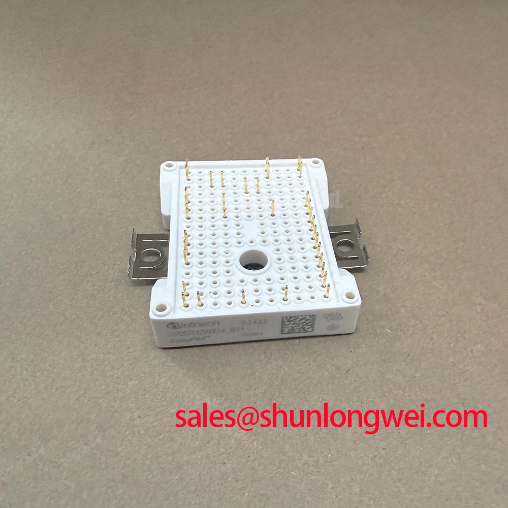
Key Technical Specifications Table
| Parameter Group | Specific Parameter | Typical Value | Unit |
|---|---|---|---|
| Absolute Maximum Ratings | Collector-Emitter Voltage ($V_{CES}$) | 1200 | V |
| Continuous DC Collector Current ($I_C$) | 25 ($T_C=100^circ C$) | A | |
| Repetitive Peak Collector Current ($I_{CRM}$) | 50 | A | |
| Electrical Characteristics (Inverter) | VCE Saturation Voltage ($V_{CEsat}$) | 1.85 ($T_{vj}=25^circ C$) | V |
| Gate Threshold Voltage ($V_{GEth}$) | 5.0 to 5.8 | V | |
| Total Gate Charge ($Q_G$) | 0.20 | µC | |
| Thermal and NTC Data | Thermal Resistance, Junction-to-Case ($R_{thJC}$) | 1.05 (IGBT per device) | K/W |
| NTC Rated Resistance ($R_{25}$) | 5.00 | kΩ |
Frequently Asked Questions (FAQ)
Q1: What are the benefits of the integrated thermistor in the FP25R12W2T4_B11?
The integrated NTC thermistor provides real-time monitoring of the module’s internal temperature. This allows for proactive thermal management and protects the IGBT4 chips from overheating during transient load conditions.
Q2: How should the heat sink be calculated for this 1200V IGBT module?
Engineers must account for both conduction and switching losses, totaling the maximum power dissipation ($P_{tot}$). Using the junction-to-case thermal resistance ($R_{thJC}$) provided in the data sheet, the designer can determine the required thermal resistance of the heatsink-to-ambient to keep the junction temperature below the $150^circ C$ continuous operating limit.
Q3: Does the module support solderless assembly?
Yes, the “B11” suffix indicates the use of PressFIT pin technology. This allows for a solderless connection to the PCB, which increases mechanical reliability under vibration and eliminates the thermal stress associated with wave soldering processes.
Closing Statement
The FP25R12W2T4_B11 is a comprehensive engineering solution that consolidates the rectifier, brake, and inverter stages into a single, high-reliability package. By leveraging the efficiency of Trenchstop IGBT4 technology and the assembly advantages of PressFIT pins, it empowers designers to build more compact and thermally efficient industrial power conversion systems without compromising on short-circuit ruggedness or insulation integrity.