Mitsubishi CM2500DY-24S: High-Efficiency 1200V 2500A Dual IGBT Module for Megawatt-Scale Power Systems
Mitsubishi CM2500DY-24S | 1200V 2500A Dual IGBT Module
Introduction to Megawatt-Scale Efficiency
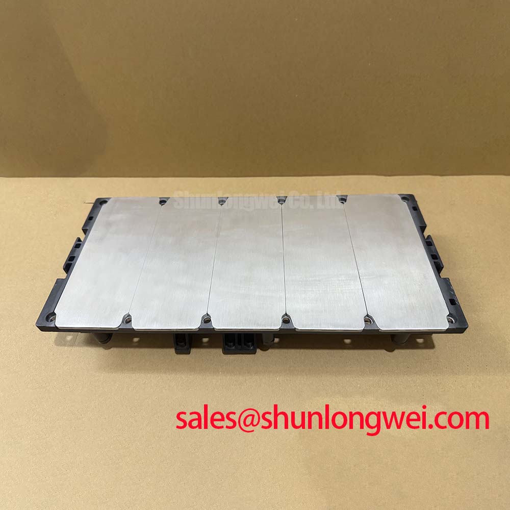
The Mitsubishi CM2500DY-24S is a high-power dual IGBT module specifically engineered for megawatt-scale power conversion systems. Utilizing the advanced 6th Generation CSTBT™ (Carrier Stored Trench-Gate Bipolar Transistor) technology, this module achieves a remarkable 2500A collector current rating within a standard dual package. This design enables engineers to achieve superior power density while maintaining low conduction losses, effectively addressing the challenges of footprint reduction in large-scale industrial hardware.
- Core Ratings: 1200V | 2500A | 1.8V VCE(sat) (typical at 125°C)
- Engineering Value: Significant reduction in conduction losses via CSTBT technology and a high 4000V isolation voltage.
- User Intent: For engineers asking how to minimize footprint in multi-megawatt converters, the CM2500DY-24S provides an all-in-one dual-switch solution that reduces the need for complex multi-module paralleling.
Download Official Datasheet (PDF)
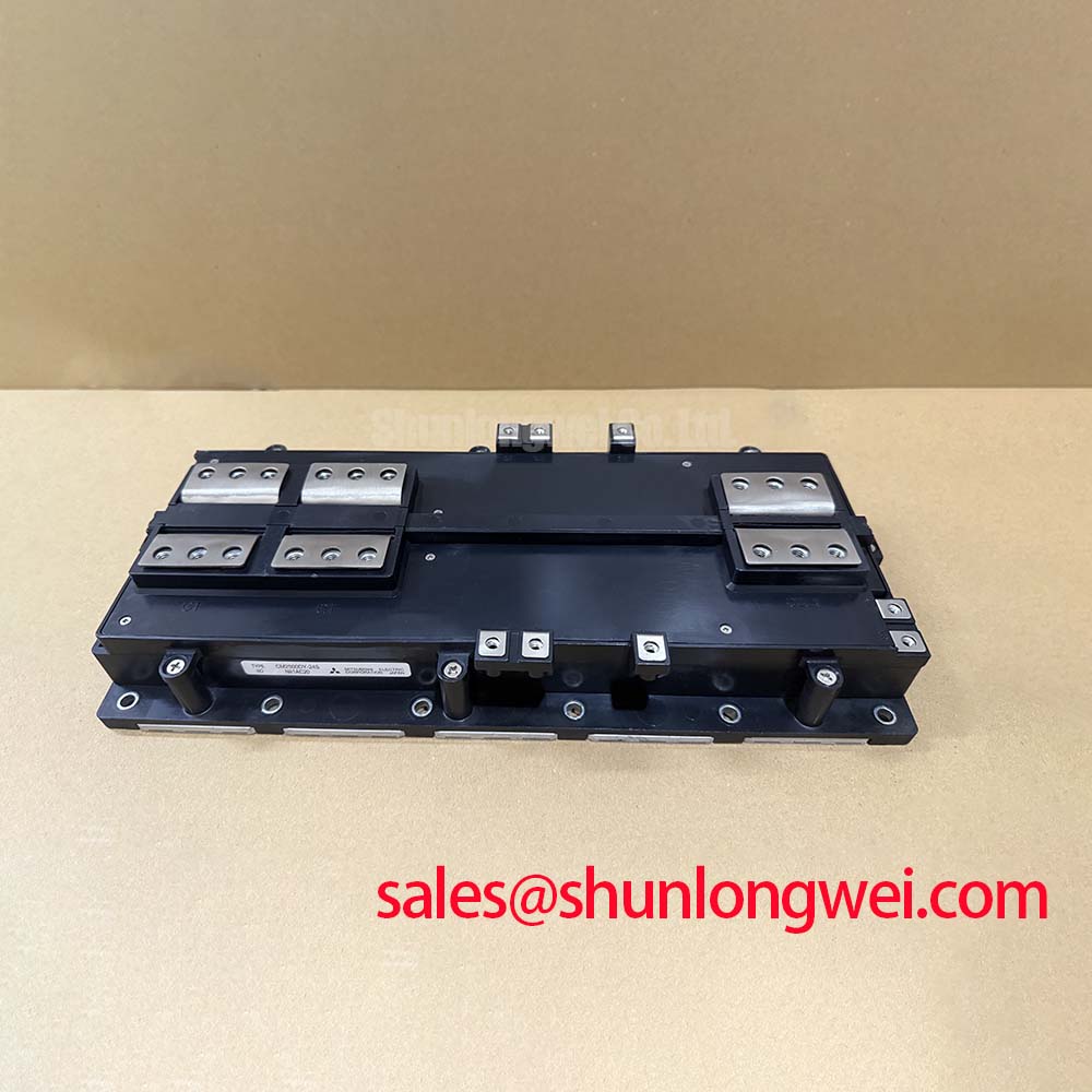
Technical Analysis: CSTBT™ and Thermal Performance
The defining characteristic of the CM2500DY-24S is the implementation of Mitsubishi’s CSTBT™ architecture. By optimizing the carrier distribution within the trench gate structure, the module achieves a lower on-state voltage ($V_{CE(sat)}$) than previous generations. This directly translates to lower thermal stress during continuous high-current operation. To better understand its efficiency, one can use a highway analogy: imagine the CSTBT structure as an advanced traffic management system that ensures vehicles (charge carriers) are perfectly spaced and moving at maximum speed. Without this storage effect, carriers would “jam” at the junctions, increasing resistance and generating excessive heat.
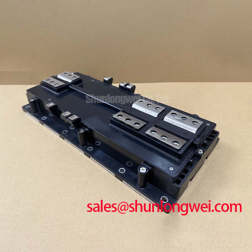
Furthermore, the thermal management of a 2500A device requires precision. The module features an isolated baseplate with a very low junction-to-case thermal resistance ($R_{th(j-c)}$). In high-power designs, even a millidegree of difference can impact long-term reliability. Addressing parasitic inductance is also critical here, as the high current levels mean even small stray inductances can cause significant voltage spikes during switching ($V = L cdot di/dt$). The internal busbar layout of the CM2500DY-24S is optimized to mitigate these effects, ensuring a stable Safe Operating Area (SOA).
Optimized Application Scenarios
- Megawatt-Scale Wind Turbines: High current density allows for compact nacelle-integrated converters where space is at a premium.
- Large-Scale Solar Inverters: The low $V_{CE(sat)}$ enhances overall system efficiency, maximizing yield in utility-scale PV farms.
- High-Power Industrial Drives: Ideal for heavy industrial motor control where robustness and high current handling are non-negotiable.
- Static VAR Compensators (SVC): The dual-switch configuration simplifies the design of large reactive power compensation systems.
Best Match Conclusion: This module is the optimal choice for applications requiring over 2MW of power conversion per inverter stack using liquid-cooled heatsinks.
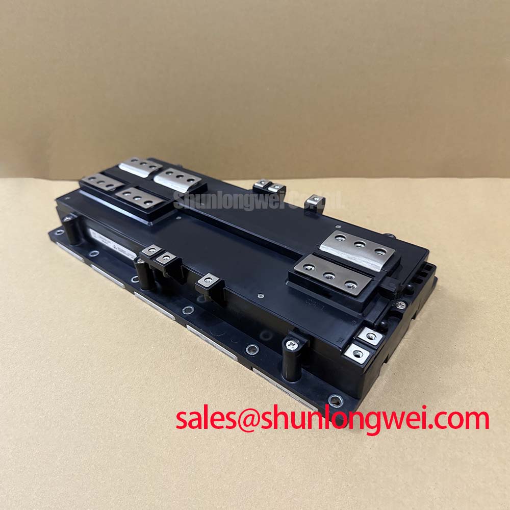
Key Specifications Table
| Category | Parameter | Value (Ratings) |
|---|---|---|
| Absolute Maximums | Collector-Emitter Voltage ($V_{CES}$) | 1200V |
| Collector Current ($I_C$) | 2500A | |
| Isolation Voltage ($V_{isol}$) | 4000V (AC, 1 min) | |
| Electrical Traits | VCE(sat) @ $T_j=125^circ C$ | 1.80V (Typical) |
| Gate-Emitter Threshold ($V_{GE(th)}$) | 6.0V – 7.5V | |
| Thermal Traits | Thermal Resistance $R_{th(j-c)}$ (IGBT) | 0.011 K/W (Max) |
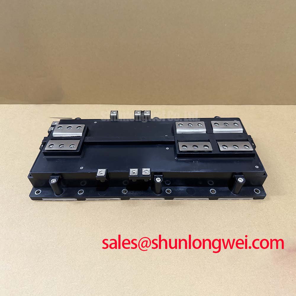
Engineer’s FAQ
Q1: What cooling strategy is recommended for the CM2500DY-24S at full load?
A: Given the 0.011 K/W thermal resistance and massive 2500A rating, liquid cooling is highly recommended. Forced air cooling is generally insufficient for the heat dissipation required when switching such high currents at industrial frequencies.
Q2: Can multiple CM2500DY-24S modules be connected in parallel?
A: Yes. However, since $V_{CE(sat)}$ has a positive temperature coefficient, it naturally aids in current sharing. Still, careful attention must be paid to symmetrical gate drive cabling and busbar layout to avoid current imbalances due to inductance mismatches.
Q3: What are the torque specifications for the power terminals?
A: The main power terminals use M6 screws. According to the Mitsubishi mounting guidelines, the tightening torque should be strictly maintained within the range of 3.5 to 4.5 N·m to ensure low contact resistance without damaging the internal ceramic substrates.
Compliance and Reliability
This module integrates high-performance Free-Wheeling Diodes (FWDi) with soft recovery characteristics, essential for reducing EMI and voltage stress during inductive load switching. The CM2500DY-24S adheres to strict industrial standards for thermal and power cycling, making it a reliable building block for modern energy infrastructures. By utilizing trench gate evolution, Mitsubishi has produced a module that balances switching speed with extreme current capability, empowering engineers to push the boundaries of high-power system design.