Mitsubishi CM400DY-12H 600V 400A Dual IGBT Module: Technical Specifications and Performance Overview
Mitsubishi CM400DY-12H Dual IGBT Module: 600V 400A Specs
Introduction to the Mitsubishi CM400DY-12H High-Power Module
The Mitsubishi CM400DY-12H is a high-current dual power semiconductor module configured as a half-bridge (dual) circuit. It belongs to the Mitsubishi H-Series, specifically engineered for high-frequency switching and robust thermal performance in industrial environments. By integrating two IGBTs with their respective free-wheeling diodes into a single isolated package, this module provides a streamlined solution for high-power inverter designs where space and reliability are primary constraints.
- Core Ratings: 600V VCES | 400A IC | 1100W PC
- Key Advantage: Isolated copper baseplate significantly improves heat transfer efficiency while simplifying multi-module mounting.
- Design Efficiency: Low drive power requirements reduce the complexity of the gate driver circuitry.
Download Official CM400DY-12H Datasheet (PDF)
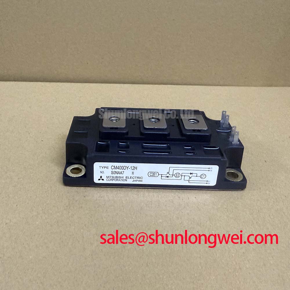
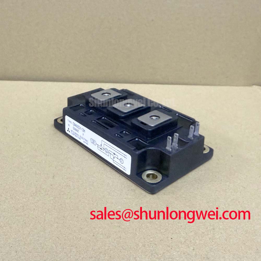
Technical Analysis of Thermal and Switching Performance
The engineering value of the CM400DY-12H lies in its balance of high current density and thermal stability. The collector-emitter saturation voltage (VCE(sat)) is typically rated at 2.4V (at 400A, 25°C). This parameter is critical because it dictates the conduction losses during the “on” state. For engineers, managing these losses is vital to preventing IGBT failure modes related to over-temperature stress.
Thermal management is further enhanced by the use of isolated baseplates. The thermal resistance junction-to-case (Rth(j-c)) for the IGBT part is 0.11°C/W. To understand this significance, one can use a thermal analogy: think of thermal resistance as the width of a highway. A lower resistance value provides a wider “thermal highway,” allowing heat to flow away from the silicon die to the heatsink much more effectively, preventing the “bottleneck” that causes localized hotspots and eventual device burnout.
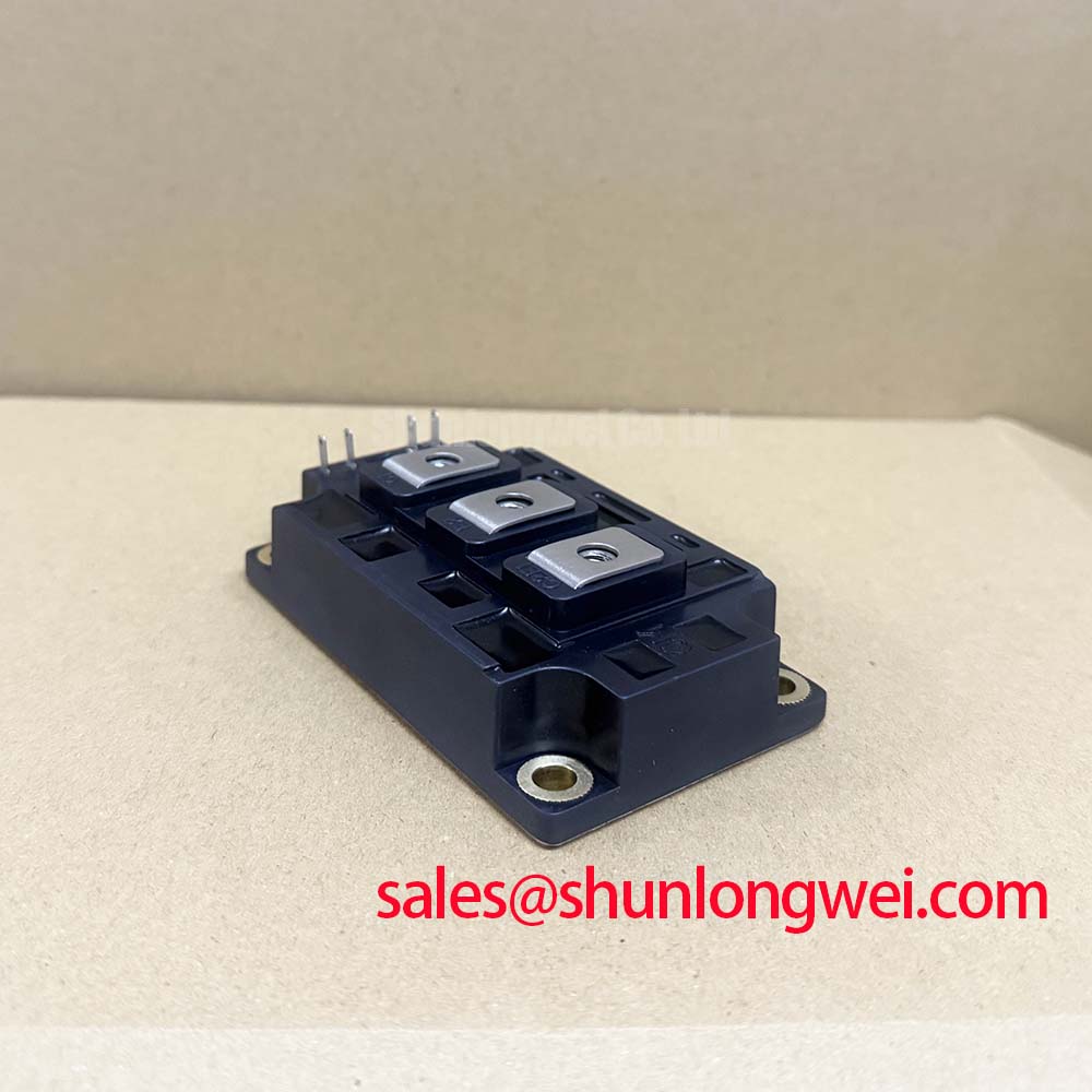

The switching characteristics also merit attention. The module features a typical turn-off delay time of 300ns. When optimizing IGBT performance, this relatively fast switching capability allows the CM400DY-12H to be used in converters operating in the 10-20 kHz range without incurring excessive switching losses, which is ideal for many industrial motor control applications.
Optimized Application Scenarios
- AC Motor Drives: The 400A rating provides substantial headroom for industrial motor starting currents and variable speed control.
- Uninterruptible Power Supplies (UPS): Fast switching and high current density enable high-efficiency power conversion in double-conversion UPS systems.
- Solar Inverters: Suitable for the central inverter stage of mid-range photovoltaic systems where 600V bus voltages are standard.
- Welding Power Supplies: The robust DY-package handles the high thermal cycling demand often found in industrial welding equipment.
Best Matching: High-performance 480V/600V three-phase inverters requiring a minimum 400A continuous current handling per phase leg for industrial-grade motor control stability.
Key Specifications of CM400DY-12H
| Category | Parameter | Value (Typ/Max) |
|---|---|---|
| Absolute Maximums | Collector-Emitter Voltage (VCES) | 600V |
| Collector Current (IC) | 400A | |
| Collector Dissipation (PC) | 1100W | |
| Electrical Characteristics | Saturation Voltage VCE(sat) | 2.4V (Typ) |
| Gate-Emitter Threshold VGE(th) | 4.5V – 7.5V | |
| Thermal Characteristics | Thermal Resistance Rth(j-c) IGBT | 0.11°C/W (Max) |
| Contact Resistance Rth(c-f) | 0.02°C/W (Typ) |
Engineer FAQ
Q1: What is the maximum junction temperature for the CM400DY-12H?
A: The datasheet specifies a maximum operating junction temperature (Tj) of 150°C. For long-term reliability, engineers typically design for a continuous Tj below 125°C.
Q2: How do I calculate the heatsink requirements for a 400A load?
A: Heat dissipation (Ploss) is calculated by summing conduction and switching losses. Conduction loss is roughly IC × VCE(sat). At 400A and 2.4V, conduction loss is ~960W. You must select a heatsink where Rth(f-a) ≤ (Tj(max) – Tambient) / Ploss – (Rth(j-c) + Rth(c-f)).
Q3: Does the module require a negative gate drive voltage for turn-off?
A: While the threshold voltage is positive, applying a negative bias (typically -5V to -15V) during turn-off is recommended to prevent parasitic turn-on caused by Miller capacitance in high dV/dt environments.
The Mitsubishi CM400DY-12H remains a cornerstone for industrial power systems requiring dependable 600V/400A performance. Its isolated infrastructure and consistent electrical parameters provide engineers with a predictable foundation for developing efficient, high-capacity power converters.